Select The Right Valves For Adsorption Processes
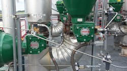
Many plants rely on adsorption to remove or separate specific components of a liquid or gaseous mixture. This mass transfer process typically involves multiple valves (Figure 1). Stroking frequency of those valves can exceed 60,000 cycles per year and maintaining industrial gas purity and efficiency requires tight shutoff to Class VI.
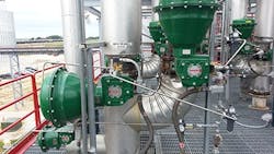
Figure 1. Reliable operation requires multiple specialty valves designed for high cycles.
Many problems occur from using the wrong valves. Poorly performing valves can lead to increased maintenance, unit trips and decreased efficiency. For example, when surveying ethanol producers from around the world, some of the most commonly reported maintenance problems related to adsorption include:
• poor control and reduced cycle life due to oversized butterfly valves;
• accelerated bearing wear, often seen after only a few months;
• multiple mechanical failures because of inferior valve-actuator-positioner linkages; and
• inadequate performance from low-quality valve positioners in both the adsorption and regeneration cycles.
Improper selection of control valve assemblies for adsorption processes can cause unscheduled downtime. During this downtime, a typical 50-million-gal/yr ethanol facility can suffer more than $10,000/hr in lost revenue.
So, we’ll look at how to select the proper valves. But, first, let’s begin with some adsorption basics.
How Adsorption Works
Adsorption is the adhesion of atoms, ions or molecules to a solid surface. This binding primarily takes place on the walls of a porous material. The component held within the pores then is purged from the adsorbent bed.
There are three common types of adsorption regeneration processes: pressure swing adsorption (PSA), temperature swing adsorption (TSA) and vacuum pressure swing adsorption (VPSA).
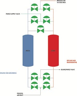
Figure 2. Simple pressure-swing adsorption process switches between two beds — with one online while the other is regenerating.
Figure 2 shows a simple PSA scheme for air separation; it uses two beds of molecular sieves, with one adsorbing and the other regenerating at any given time. An air separation process primarily aims to separate oxygen or nitrogen. During the production step, air goes into a cylinder containing beads of adsorbent material at pressure. During the regeneration step, a small amount of nitrogen or oxygen flushes the waste gas through an exhaust port, preparing the vessel for another production cycle.
A common use of the TSA process is for moisture removal. Wet gas is pumped into a cylinder filled with adsorbent beads at pressure. After adsorption of the moisture, dry gas leaves the vessel. Once the beads are loaded with moisture, the bed is taken offline for regeneration. Here, heated purge gas raises the temperature of the loaded bed, driving off the adsorbed moisture. Before returning online, the desorbed bed must cool down so that it can adsorb again in the next cycle.
Valve Roles
Now, let’s look at the various valves required in an adsorption process.
Switching valve. It cycles the beds between online and offline. This valve is very important because, if incorrectly controlled, it can fluidize or fluff the adsorption beds, causing damage to the adsorbent materials and the bed itself. Such fluffing can be a very expensive problem and must be prevented.
Cycle times depend on the regeneration method. In the TSA process, the cycle time is around eight hours. In contrast, the PSA and VPSA switching processes take one to three minutes. The marked difference reflects how much faster pressure changes can take place than temperature ones.
Dump/purge valve. This removes impurities from the process. Because the impurities leave as off-gas, this often is called the off-gas process.
Feed gas valve. It introduces feed gas (air, hydrogen, biogas, etc.) into the clean adsorbent bed. It opens simultaneously with the product valve to ensure the feed gas passes through the bed, allowing the bed to adsorb impurities to make the finished product.
Purge supply valve. This enables purge gas to enter the beds by connecting bed A to bed B. Gas then flows from the higher pressurized bed into the lower pressurized one. Keeping pressure in the lower pressurized bed as low as possible minimizes the impurity partial pressure and maximizes adsorbent regeneration. This valve also can perform equalization between the beds.
Product/repressurization valve. It permits the final product to pass through the top of the adsorption beds and then into product storage tanks. This valve works in conjunction with the feed gas valve so that feed gas goes through the bed and gets treated before the final product leaves the vessel. It also can perform equalization between the beds.
Key Considerations
Proper selection of all adsorption valves requires adequate attention to two major concerns: tight shutoff and robust design.
Tight shutoff. If the valves don’t shut tightly, the beds will leak and, therefore, decrease the process efficiency and increase costs. A recommended practice is to specify Class VI shutoff for all valves in the adsorption process to ensure the highest process efficiency.
Typical process temperatures allow for the use of soft seals. Opting for a form of polytetrafluoroethylene (PTFE) for soft seals (Figure 3) will give the durability needed for the multitude of cycles while also providing a tight seal and Class VI shutoff. PTFE is a fairly low friction material, thus reducing the force needed to seat and unseat the valve. However, PTFE is limited to 450°F. So, if the adsorption units run above that temperature, the best option is to select a metal seal despite its drawbacks such as higher leakage rate, torque and wear. It’s critical to choose a valve with at least Class IV shutoff to ensure the smallest leakage possible as well as a hard-faced seat material to lengthen the life of seats.
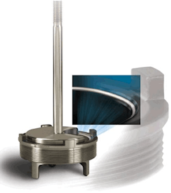
Figure 3. A PTFE seal suits most applications and can ensure tight shutoff.
Selecting a soft seal on a globe valve will allow for Class VI shutoff; additionally, it can limit wear between the seat and the plug, which also will lengthen valve life.
Robust design. This is crucial because valves must withstand a high cycle count. Not selecting a robust-enough design may lead to premature failure, which will incur increased cost through process downtime and additional equipment expenses. Choose a valve that has been tested to one million or more cycles to ensure reliability. Verify the testing took place at pressures equal to or greater than those expected in your process.
When selecting butterfly valves, check that the components in the valve’s drive train — the shaft, disk and connection to the actuator — are tightly connected to avoid any loss of motion. Loss of motion will translate to additional wear on parts that can lead to premature failure. Using a splined shaft-to-actuator connection will provide the tightest connection and least loss of motion.
The connection between the shaft and the disk must be strong and tight. The disk of the butterfly valve must contact the seat correctly to ensure tight shutoff, avoid additional part wear and minimize valve torque.
Also, consider bearings when selecting valves. PTFE-lined polyetheretherketone (PEEK) bearings are a great choice for high-cycle butterfly valves in adsorption units. These low-friction and low-wear bearings allow the control valve to operate under high pressure drops and high cycles while maintaining low torque needs from the actuator. This ensures that early bearing failure doesn’t lead to early valve failure.
However, PTFE-lined PEEK bearings also have a 450°F limit. Therefore, in some higher temperature units, you may need to opt for metal bearings. Insist upon metal bearings that use a hard material or have been hardened. Two possibilities are solid R30006 bearings or nitriding a softer material such as S31600. Both options will ensure greater life of the valve and help maintain its functionality through the high cycle demand of the adsorption process. A valve with metal bearings requires increased torque to operate, so you must select an actuator with suitably higher output torque.
When using sliding stem valves, opt for stainless steel trim with hard-facing. Hard-facing critical trim components such as the valve plug will keep wear to the minimum. Using a hard-faced plug also will minimize galling and increase valve life. Not selecting a hard-faced trim can lead to plugs getting stuck, which, in turn, will cause process downtime.
The last thing to consider when selecting both butterfly and globe valves is the packing system. It helps align the stem of a globe valve and the shaft of a rotary valve to operate and shut off properly, and, of course, also serves to prevent leaks. An adsorption process usually requires tight emissions control. Leaks to the atmosphere not only decrease efficiency but also could lead to fines. Many packing systems experience increased wear over time that can lead to greater atmospheric leaking. Using a live-loaded PTFE packing will ensure emissions are limited.
Also, consider valve assembly upgrades — such as integrated internal air passageways in actuators and linkage-less non-contact positioners — that can increase reliability. Internal air passageways obviate actuator air tubing, removing a failure point from the control valve assembly. Linkage-less, non-contact positioners eliminate problems with positioner linkage.
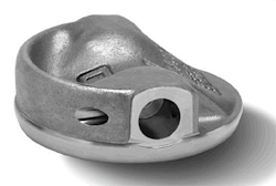
Figure 4. Butterfly valves with special disk geometry can work effectively at around 15–70% open.
In addition, valve sizing must be taken into consideration. It’s very common for valves to be oversized, which can lead to increased wear on the valve and poor control. Butterfly valves often are selected based on the process line size. However, that may be too large for the process. This is especially critical for butterfly valves where the optimal process range is within 30–60% open.
Operating outside that control range can cause the process to react too drastically to an input change. The control loop may not be able to adapt properly, which could lead to the control valve hunting for the right set point. This will upset the process and create additional wear on the control valve, both increasing costs and decreasing overall efficiency. Therefore, when selecting a butterfly control valve, ensure the operating range is within 30–60% open. If not, consider using a smaller-size control valve.
For highly demanding process conditions, some butterfly valves feature disk geometry that expands the acceptable control range to around 15%–70% open (Figure 4).
Choose Wisely
Adsorption is a high-cycle process that creates wear on valves. Proper selection of packing and seals, along with ensuring the valve design is robust enough to withstand multiple cycles, will lead to a longer life and trouble-free operation.
KEITH NEHRING is Marshalltown, Iowa-based chemical industry manager for Emerson Automation Solution’s flow control products. Email him at [email protected].