Deftly Deal With Control Valve Problems

Control valves play a critical role in keeping a process operating properly. A control valve should respond reasonably quickly — not too fast or too slow — to signals from the controller or distributed control system (DCS). Unfortunately, malfunction or misapplication of this relatively low-cost item has caused many unsafe events, some with catastrophic consequences.
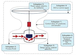
Figure 1. The number of relevant subsystems varies depending upon the type of problem.
Control valve problems arise from a wide variety of sources. A troubleshooter must strive to identify the actual source quickly and limit its impact. This paper presents a systems approach for minimizing both design issues and operating problems of control valves.
A systems approach is strategic and intuitive — and broadly applies not only to control valves but also to myriad other operating and control systems. Figure 1 shows a systems view of a control valve and its subsystems.
Simply put, issues with any of the subsystems or their interactions could cause a control valve to malfunction. Although the figure shows six subsystems, the actual number can vary depending on the nature of the problem. Here, though, let’s look at these six subsystems to examine their potential problems and how to avoid them.
Subsystem 1
This primarily consists of the control valve, its trim, packing, I/P (current/pressure) transducer, positioner and actuator. The control valve (flow element) should be selected to provide the desired flow characteristics of the valve, i.e., linear or equal percentage. Possible options include, for example, globe, ball, V-ball, butterfly, plug and diaphragm valves. Each trim has its pluses and minuses. For example, globe valves provide good flow control but incur a high pressure drop (low pressure recovery) that could cause flashing or cavitation in some liquid applications depending on their vapor pressure. Butterfly valves, on the other hand, create low pressure drop but offer limited rangeability, i.e., the ratio of maximum to minimum controllable flow. Thus, you shouldn’t consider butterfly valves if you expect large variations in production rates. Valve selection is governed by, among other things, the fluid properties (e.g., vapor pressure, viscosity, solids content or liquid entrainment in gas) and system hydraulics.
Packing design and selection is determined by pressure, temperature, fugitive emission requirements and type of valve stem movement (rotary or sliding). Packing should be just tight enough to allow smooth movement of the valve stem with minimum fugitive emissions. Packing that is too tight typically causes sawtooth response to the signal from the controller.
The three common types of actuators are pneumatic, hydraulic and electrical. Pneumatic actuators are most common; hydraulic and electrical versions generally find use in high torque applications.
Services that require accurate positioning of the valve stem (flow control) and valve opening use valve positioners. Besides providing accurate valve stem movement that corresponds to the controller signal, positioners minimize a number of friction- and linkage-related problems such as dead band, backlash and hysteresis. Positioners have progressed from simple pneumatic designs to digital or smart units that provide improved calibration accuracies and diagnostics with their communication protocols. Smart positioners largely have replaced analog devices in recent years.
Some major issues to consider are:
• Dead band, backlash and hysteresis degrade control loop performance. Because difficulties in these areas relate to mechanical linkages and friction, older valves tend to be more susceptible. Periodic calibration and maintenance help minimize their effect.
• Although not commonly an issue, undersized actuators cause valve response to be sluggish. Inadequate air pressure (discussed in subsystem 4) also leads to sluggish response.
• While a healthy gain is essential for reducing dead time or dead band of positioners, too much in positioners or controllers (say, with aggressive gain or reset settings) can create valve oscillations and degrade control loop performance. These positioners show initial overshoot to a step change from the controller.
• As a rule of thumb, control valves should be 70–75% open at full flow. Oversized valves operating at small or barely open positions cause poor control performance. Conversely, undersized control valves fail to control at full flow rates.
• Installed valve response should be linear or close to it. A nonlinear valve response, i.e., valve gain variations at different valve openings, could prompt poor performance in control loops.
Subsystem 2
This subsystem focuses on the effect of the fluid on control valves. Although the design phase takes into account relevant fluid properties, problems still may arise during operation. For example, valves could experience flashing (liquid vaporization), cavitation or other noise and vibration, erosion, corrosion and plugging. Simply put, the control valve should match fluid properties as well as operating pressures and temperatures. So, consider the following:
• If pressure at the vena contracta region, i.e., that of lowest pressure and highest velocity, falls below the vapor pressure of the liquid, vapor forms.
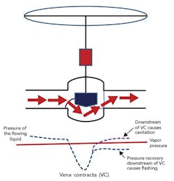
Figure 2. The amount of pressure recovery after the vena contracta determines the nature of potential issues.
As shown in Figure 2, downstream of the vena contracta, some pressure recovery occurs. If the recovered pressure is below the vapor pressure of the liquid at the flowing temperature, flashing takes place. Flashing erodes the valve and could produce noise. If the recovered pressure exceeds the liquid vapor pressure, vapor bubbles collapse, causing cavitation, noise and vibration. Repeated exposure to cavitation leads to severe damage to valve, valve body and piping if the collapse process continues downstream of the valve.
To remedy flashing/cavitation, reduce the pressure drop either by changing operating conditions, relocating the valve or switching to a low-pressure valve. Additionally, consider trim designs that, in essence, involve multi-stage reduction of pressure or moving the vapor collapse and bubble formation away from valve internals or use of metallurgy able to withstand cavitation damage.
• High pressure drops or cavitation conditions generate noise, often of high pitch. Process modifications to reduce pressure loss, while the most desirable remedy, may not always be practicable. In such cases, consider a number of other methods including, for example, trim modifications, diffusers, silencers and acoustic insulation. An international standard, IEC 60534-8-3, offers a five-step empirical method for predicting noise that is suitable for valve and accessory sizing and design; Reference 1 provides details.
• Valves in abrasive slurry applications experience erosion and plugging in the flow path and packing. Among the options to consider are ball, lined butterfly and angle valves. The optimum choice depends on the system hydraulics; the objective is having trim that is nearly linear. In addition, desirable features include, for example, full pipeline opening, unobstructed flow path, adequate pressure/temperature rating, self-draining, rangeability and actuator stem positively sealed from the process [2].
Subsystem 3
Design focuses on a number of issues including, but not limited to, valve type and size, installed flow characteristics, metallurgy, protection against excessive noise, vibration and cavitation or flashing, valve accessories (e.g., I/P transducer, positioner and actuator), fail-safe mode and seat leakage class.
Today, designers generally use control valve sizing software based on empirical equations from IEC60534-2-01/ISA 75-01-01 or the equivalent. These equations account for a number of parameters such as piping geometry, pressure recovery, choked flow, vibration, noise, cavitation or flashing. Software output includes flow coefficient (Cv), trim, metallurgy, packing and valve accessories. Valve sizing always should take into account system hydraulics (pressure drops in piping and in the control valve at the range of low rates) with the objective of getting an installed flow characteristic that is linear or near-linear. Consider the following [3]:
• The control valve opening should vary between 20% and 80%.
• Try to keep control valve gain (change in flow/change in valve position) at 1.
• Hold the ratio of maximum gain to minimum gain of the control valve to under 2.
• Avoid gains less than 0.5 and more than 3.
Subsystem 4
A control loop consists of a control valve and other elements (Figure 3). While legacy systems used a 4–20-mA unidirectional signal from the controller to the control valve, today’s systems offer several communication protocols such as Foundation Fieldbus, Profibus and HART (4–20-mA and digital communications). Some noncritical or less critical control applications now rely on wireless transmissions.
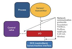
Figure 3. This consists of a number of elements linked by a network communication protocol.
Consider the following:
• The controller or DCS signal directly affects the action of the control valve. Aggressive tuning (high gain, reset or rate) can prompt valve oscillations while, conversely, low gain can cause sluggish valve response. The open literature contains a number of rules of thumb for tuning that can be used along with auto-tuner software and historians. You must think through potential effects on your process before applying step changes to load disturbance or, less preferably, change in set point to get an approximation for gain, reset and rate values. Rate (derivative) mode isn’t suitable for most control applications except temperature or pH.
• Aggressively tuned positioners also will lead to valve oscillations.
• Valve packing that is too tight causes hesitation from the control valve and often results in sawtooth response. In addition, deposits from the process stream, excessive dust or ice can hinder movement of valve stem.
• Although twisted pair and shielded wiring commonly protect against electromagnetic interference (EMI), other problems such as loose wiring connections or improper grounding can create erratic valve response. Increasingly, plants opt for fiber optic wires to avoid these problems.
• While scan rates of the communication protocols (e.g., HART and fieldbus architectures) have not been a problem in most control loops, at the system design stage you must carefully assess scan rates essential for fast loops such as those for flow or pressure.
• DCSs and their protocols enable remote calibration, troubleshooting and retention of relevant documentation, improving maintenance efficiency. Use remote calibration in conjunction with field visits to control valves as appropriate.
Subsystem 5
Control systems typically run on 24 V DC, stepped down and converted from 120 or 220 V AC systems. To enhance reliability, they usually feature redundant power supplies and battery backup systems. The design stage should address a number of potential problem areas including voltage regulation, total system load (power consumption), EMI, moisture and dirt ingress (which can be prevented by suitable NEMA-rated enclosures or protective coatings), and lifecycle maintenance and upgrade issues.
The capacity and quality of the instrument air supply are critically important; the instrument air should be supplied at adequate pressure and free of oil, dirt and moisture. Conformance to “Quality Standard for Instrument Air,” ANSI/ISA-7.0.01, usually is desired.
Instrument air systems comprise an air compressor (with adequate spare capacity), intercoolers and knockout drums for removing free water, desiccant dryers, an air receiver and associated instrumentation. Air compressors come in different types such as reciprocating, centrifugal and rotary screw, with selection based on pressure and capacity requirements; oil-free compressors generally are preferable to avoid risks of air contamination. Pressure and dew points for the instrument air near the control valve actuators/positioners vary. Pressure of 20 psig is common. Many plants use a temperature of -40°F because that’s the dew point provided by heatless desiccant dryers. ANSI/ISA-7.0.01 requires a dew point at least 18°F below the minimum ambient temperature.
Air supply tubing usually is Type 316 stainless steel. Some low-pressure applications use plastic tubing, but it is prone to kinks and leaks.
Keep in mind the following points:
• Free water, dirt or oil in instrument air cause control valves to respond erratically.
• Air leaks and inadequate pressure at the control valve lead to sluggish response; too high a pressure makes the response erratic.
• Ensuring reliability demands regular field inspection and maintenance of air and electrical systems.
Subsystem 6
Environmental considerations for control valves and accessories include protection from temperature and weather extremes as well as from dirt. Proper enclosures must be provided for environmental protection. Several other factors that merit consideration are:
• Valve leakage rate. ANSI-FCI 7.2 classifies leakage rate into classes II through VI, with the allowable leak rate decreasing as the class size increases. Safety-critical applications could require a leak class as high as V or VI.
• Safe action on power failure. The particular application determines what is suitable. For example, control valves supplying heating medium to a reboiler preferably would be air fail closed (AFC) while those handling cooling water to an overhead condenser would be air fail open (AFO). Because of safety/operability considerations, some other applications use air fail last (AFL). Quick closure of large valves could cause hydraulic shock. For restart (after restoration of air supply), you often must provide safeguards to prevent an abrupt increase in valve flow. For example, suddenly sending full heating medium or steam flow to a reboiler can damage internals of a distillation column.
• Fire protection. For safety-critical applications, ensure adequate fire protection of the valve and accessories.
• Human factors. Consider issues such as lighting in the area and accessibility.
Be Systematic
Efficient and safe plant operation depends on proper performance of control valves. A systems approach can help to quickly identify and resolve problems that might arise with them.
GC SHAH is a senior consultant at Wood, Houston. E-mail him at [email protected].
REFERENCES
1. “Control Valve Handbook,” 5th ed., Emerson Automation Solutions, Marshalltown, Iowa (2017).
2. Liptak, B., “Control Valves for Slurry Service,” Control (April 2007).
3. Monsen, J., “Installed Gain as a Control Valve Sizing Criterion,” Valin, San Jose, Calif. (Jan. 2013).