Centrifugal pumps comprise over 90% of all pump installations in the chemical industry. They have proven to be the most economical pumps in various services; they require much less maintenance and operational efforts than other pump types. A centrifugal pump usually includes a casing (housing) having a cavity, a suction and a discharge; a shaft located in the cavity has an impeller (or impellers) positioned to receive liquid from the suction and exhaust that liquid to the discharge. Unfortunately, problems with shaft seals often arise — indeed, seals cause more than half of all unscheduled shutdowns of centrifugal pumps.
Many plant operations can’t tolerate any leakage of liquids for safety, environmental or economic reasons. Yet, some difficult services pose a nightmare for seal selection. This has spurred the development of sealless centrifugal pump technologies.
Sealless versions now are available for all common centrifugal pump designs: end-suction top-discharge used for single-stage pumps; top-suction top-discharge used for multi-impeller horizontal pumps; and multi-impeller vertical pumps (sometimes with 30 impellers or more) used for high-pressure applications.
Magnetic drive units are the most common sealless pumps at chemical plants but submerged motor pumps also find wide use. Both types of pumps have proven themselves over many years in a variety of different services.
Magnetic Drive Pumps
These are close-coupled pumps that can be quickly and easily stripped and rebuilt in the field; most often they don’t require traditional alignment. Such units usually handle corrosive or difficult liquids; materials of wetted parts must suit the particular liquid.
Magnetic drive pumps have some limitations and disadvantages. For instance, they don’t come in large sizes and with high power ratings. Many internally circulate the liquid being pumped for bearing lubrication and cooling; so, those pumps aren’t appropriate for some applications, such as ones involving liquids susceptible to forming scale.
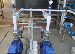
Figure 1. Such units are the most common sealless pumps used at chemical plants.
Magnetic drive pumps also should not run dry. While that’s more or less true for centrifugal pumps in general, a magnetic drive pump is more vulnerable to damage from dry running because the pump liquid provides bearing lubrication. Some manufacturers have developed bearing materials and coatings that are more forgiving of upset conditions and can run dry for a limited time; this also depends on the particular pump’s details and service. Upset conditions often result in some liquid remaining in the pump; this aids in bearing lubrication and prevents the bearings from breaking during brief dry-run periods. Hopefully, advances in bearing technology eventually will allow dry running for extended periods.
The magnet system transmits all the pump power and so requires special attention. A straddle-mounted design with bearings on either side of the inner magnet provides excellent stability and operation; this modern design reduces radial loading and allows the pump to better tolerate off-peak operation — and is far superior to the old-fashioned overhung inner magnet design.
Recirculation Flow
Every magnetic drive pump has a recirculation flow system — usually either discharge to suction or discharge to discharge. In the discharge-to-suction design, the fluid enters the magnetic coupling area at a high-pressure discharge point and returns to the bulk flow at the suction eye of the impeller. In the discharge-to-discharge design, the fluid enters the magnetic coupling area at a high-pressure discharge point and returns to the bulk flow at a point behind the rear shroud of the impeller. Each design has its advantages; so, make the choice between them on a case-by-case basis. Other recirculation flow paths and designs also are available in special magnetic drive pumps.
In the discharge-to-suction design, the flow is routed to the suction through either thrust balance holes in the impeller or through a hole along the axis of the pump shaft. The differential pressure between the recirculation inlet and return locations drives the recirculated liquid at high velocity. As the differential pressure rises, the internal flow rate increases but at a decreasing rate. The internal flow will reach a maximum beyond which any additional increase in differential pressure will have negligible impact. This occurs when friction losses begin to become the dominant factor affecting flow. The observed internal pumping effects primarily are caused by the action of the inner magnet ring and thrust washers.
The differential pressure between the recirculation inlet and return locations is lower for the discharge-to-discharge design, so it creates less recirculation velocity. However, discharge-to-discharge recirculation provides a larger flow path. Moreover, its flow pattern is characterized by high localized pressure and little interference with suction flow. Overall, the mass flows are comparable. Internal pressures in both systems prevent flashing of most liquids at the magnetic coupling interface or internal bearings.
Discharge-to-suction recirculation tends to have better impeller thrust balancing characteristics due to its routing of the flow through the impeller eye balance holes. However, this provides minimal advantage and, with the growing use of silicon carbide thrust bearings, isn’t a significant factor.
Discharge-to-suction recirculation also tends to flush solids better due to its higher velocities. In general, pumps with silicon carbide bearings can handle a higher level of solids because these bearings stand up well to most commonly encountered abrasive solids. A pump equipped with discharge-to-discharge recirculation typically has a lower required net positive suction head (NPSHR) because the recirculation return flow doesn’t interfere with fluid flow through the suction eye.
Thrust Balanced Pumps
The design of such units ensures virtually no thrust-bearing load; this leads to high reliability and long pump life. One type of thrust balancing system has a valve with a ring extending from the impeller hub; this is used to define a variable-sized vent between the ring and shaft. The pump usually includes wear rings with axially extended rings that permit the thrust balancing system to operate within a range of axial positions, with the particular one chosen based upon the operating point of the pump and specific gravity of the fluid.
Balancing axial hydraulic thrust on an impeller (or impeller assembly) reduces or eliminates maintenance of axial thrust bearings by generally maintaining spatial axial separation between members of any axial thrust bearing during normal pump operation. Moreover, the thrust balancing system increases mechanical efficiency and decreases torque-driving requirements of the pump by cutting friction associated with axial thrust bearings. In particular, the thrust balancing system may reduce the activity (for example, duty cycle) of axial thrust bearings or avoid the need for axial thrust bearing(s) altogether. However, a conservative engineering approach is to replace a conventional axial bearing with an auxiliary axial bearing intended for intermittent use in conjunction with the thrust balancing system. Nevertheless, in general, many sealless pumps (whether magnetic drive, submerged motor or another type) don’t have axial (thrust) bearings.
This system also could include a radial bearing positioned in an impeller recess at or near the center of gravity of the pump upstream from the thrust balancing valve, i.e., further toward the discharge pressure or direction of fluid flow, to improve resistance against dry running and prevent flashing of the pumped liquid.
Submerged Motor Pumps
In these units, the motor and hydraulic sections are directly coupled with a common shaft and fully submerged in the pumped fluid. This isolates the unit from the atmosphere and thus completely eliminates the need for seals or couplings; pumped fluid fills motor gaps and voids. There’s practically no leakage. Design of bearings and their compatibility with the pumped liquid is important.
The primary reason for submerged motor pumps’ popularity is their inherent safety and reliability. Another benefit is the avoidance of alignment problems normally associated with pumps that use couplings. In addition, the liquid in which the assembly is submerged acts as effective sound insulation; these pumps operate very quietly.
Some of these pumps are long multistage vertical units — e.g., one plant uses a 15-stage pump to move liquid from a high-pressure storage tank. A usual design has three radial ball bearings along the pump shaft line. This construction yields a stiff rotor perfectly guided on multiple points. Bushings in all non-bearing carrying stages provide additional damping. The stiff and damped rotor dynamics enable safe pump operation in different steady state and transient situations.
Many submerged motor pumps can’t or don’t use thrust bearings because of the low load capacity of these bearings or previous failures. Instead, a specially designed balance drum assembly usually compensates for axial forces. Such an assembly should meet the requirement of the axial thrust balancing in all anticipated conditions, i.e., for whole operating range considering flow, head, etc.
Submerged motor pumps come in a wide variety of power ratings and sizes. As a very rough indication, motors range from 50 kW to as much as 3.5 MW and capacities extend to 4,000 m3/h and over 4,000 m of head. The motors are a unique design. The starting current required is approximately 6 to 6.5 times the full load current because of the amount of torque required for starting the pump. Soft starters, autotransformers and variable frequency drives have worked very well in many different applications to reduce the starting current. However, proper setup of starting parameters in any current-reduction-type starting system is important.
Most submerged motor pumps today are vertical types whose hydraulic design evolved from that of standard American Petroleum Institute (API) vertical in-line or other API vertical centrifugal pumps. Multi-vaned diffusers rather than a volute casing usually provide diffusion. The diffusers can be axial flow (to maintain smaller diameters) or radial flow (to maintain shorter stage lengths). Impellers are of radial- or mixed-flow (Francis) type, closed shrouded design and the hydraulic stages are radially split. The pumps can have up to 25 stages (or sometimes more) to satisfy service requirements. Typically, the first stage is a high-specific-speed axial flow inducer, used to improve NPSHR performance.
Making A Choice
Magnetic drive pumps usually suit small- and medium-sized services involving corrosive, toxic, dangerous and other troublesome liquids that should not contact the environment or the electric motor. On the other hand, submerged motor pumps can handle medium- and large-size applications with clean and usually non-corrosive liquids so long as the fluid doesn’t cause difficulties if delivered to the electric motor.


