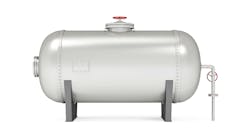
Have you ever done a double-take when looking at an inspection photograph? I certainly did when an engineer at a valve manufacturer sent me an inspection photograph and asked, “See anything wrong with this picture?” “Yeah,” I replied. Someone had installed two expansion relief valves back-to-back on the body bleed of a twin-seated plug valve used for isolation in our gasoline tank farm. The valve casting safety port was cracked because expansion flow was choked. “Dumb, really dumb,” I remarked. How did this get by?
I fervently believe that all engineering problems have their roots in design. So, let’s look at some guidelines for designing relief systems. First, carefully examine any design involving two relief devices (including rupture discs) back-to-back.
Second, grill anyone who wants to slap in another small device instead of replacing the whole rig with a single larger device. The argument usually made for this approach is that small valves are easier to get and less expensive. However, standards tend to punish this sort of reasoning. According to Section VIII, Divisions 1 and 3 of the ASME Boiler and Pressure Vessel Code and Part 1, Section 2 of API Recommended Practice (RP) 520, you can set a single valve to 10% above the maximum allowable working pressure (MAWP) for all relief scenarios except fire, where 21% is allowed. There’s often some confusion with the set pressures of multiple valves — another reason to avoid them.
The Society of Petroleum Engineers (SPE) offers some useful guidelines. Namely, you should: 1) set the smallest capacity valve at the lowest pressure; 2) set the “primary” device, i.e., the first one that opens, no higher than the MAWP; 3) stage valves between a maximum set pressure of 5% above the MAWP and the set pressure of the primary device; and 4) also apply rules 2 and 3 for the fire case but use a maximum set pressure of 10% above MAWP for that case. It also recommends minimizing chatter — but chatter is unavoidable with multiple valves.
In effect, using multiple devices restricts the operating pressure for the system. Why? Because unless a relief valve has a soft seal, it will start to open at about 80% of its set pressure to ensure full flow at 110% of the set pressure.
Suppose you have a MAWP of 150 psig. For a single relief valve, the set pressure is 165 psig and the maximum operating pressure is about 80% of that, around 132 psig. With two valves, the first valve opens at 150 psig while the second must open at 157 psig; so, the maximum operating pressure is only 120 psig. This not only is restrictive but could be expensive if your valves are protected by rupture discs.
Another design concern is the inlet of the relief device. According to API RP 520, Part 2, Section 4.2.2: “The total non-recoverable pressure loss between the protected equipment and the pressure-relief valve should not exceed 3% of the set pressure of the valve except as permitted in 4.2.3 for pilot-operated pressure relief valves.” Believe it or not, 10–20% of devices in many refineries break the 3% rule.
Check valves at the inlet and outlet of relief devices have raised some concern. The SPE doesn’t seem to have a problem with check valves at the inlet but API RP 520, 6th ed., Part 2, Section 6.3.2(c) excludes check valves, albeit in an off-hand way: “This outlet isolation (valve) shall never be closed while the vessel is in operation.” Note the relief devices protect vessels, not pipe. Because check valves, even swing-style ones, could rust closed, you should exclude all from outlet and inlet service.
Now, let’s consider pipe construction. First, even for a batch system, you should have double-block-and-bleed valves upstream and downstream; install an additional downstream valve for high pressure (>150 psig). Second, for any valves smaller than 3 in., insist upon socket welds to ensure stability.
I plan to cover more aspects of this topic in a future column.


