This Month’s Puzzler
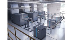
Prior to installing our last filler line, we thought our compressed air system (Figure 1) was adequate. Now, all our pressure-regulating valves (PRVs) are operating near 100% and our actuated valves are having trouble opening or closing. Our dryer is a conventional chiller dryer. The instrument air employs an additional desiccant dryer and a series of water/oil traps. Our plant standard assumes 60-psig actuators and 78-psig air.
After these problems appeared, I started investigating our plant-wide usage. I found we consume 540 scfm while we’re shut down over the weekend. Some air lines show unusual pressure drops.
Our plant uses a lot of air diaphragm pumps, not only for cleaning up spills but also for moving viscous product around the plant. We keep the product pumps separate to meet cGMP standards. Operators and mechanics seem to connect pumps wherever they want, sometimes even into instrument air lines — much to the chagrin of our instrument engineer. I’ve noticed water and oil dripping out of the air discharge of the air diaphragm pumps.
We’re planning a plant expansion soon and will want to add more pumps and more filler lines. Is there anything we must do to the compressed air system to increase its capacity and pressure?
Consider Several Projects
I have some quick suggestions that wouldn’t require a large upfront engineering study, which could be very costly. The capital costs of the below projects should be reasonable and could be phased in over a year or two if capital is constrained. We have many diaphragm pumps at our facility as well as instrument air needs and have seen the same issues over the past few years.
On the main system, complete the following:
1. Install another compressor unit and set the two units up in a master/slave relationship. We have units at our facility set to hold 125 psig and then, if the pressure drops below 110 psi, the second unit starts supplying air. Your site could set the master at 110 psi and then have the slave come on at 100 psi, ensuring air flow.
2. Upsize the feed piping after the dryer to 6 in. from 4 in. The would reduce the pressure drop from 13.83 psi to 3.82 psi, thus ensuring more air flow to the main system.
3. Remove the chilled dryer or augment it with a desiccant dryer system that would decrease the dew point, thus reducing the amount of water vapor present in the system.
4. If design allows, increase the system pressure to 125 psig. In reference to item 1 above, set the master at 125 psig and the slave at 110 psig.
As for the instrument air system, complete the following:
1. Separate out the instrument air system from the main air system via valving, thus ensuring a backup supply for the instrument air from the main compressed air system.
2. Install two compressors on the instrument air system and set them up in the same master/slave relationship as stated above. The pressure could be set at 90-psig master and 80-psig slave since a 78-psig air supply is assumed. If possible, increase the pressures based on design data of the system.
3. As far as the operators connecting diaphragm pumps on the instrument air system, remove all hose connections on the newly isolated instrument air system and plug the connections. Install, as necessary, piping with hose connections from the main compressed air system for the diaphragm pumps. And, as you always should, train the operators on the new operation.
The air diaphragm pumps leave something to be desired. You might consider installing positive displacement pumps with variable speed drives for flow control. We are doing this at our facility with great success.
Vincent Suttmiller, plant engineer
Lubrizol Advanced Materials, Inc., Paso Robles, Calif.
Tackle Four Problems
You’ve run into a situation common with most compressed air systems: they work until they don’t because they’re ignored. You immediately should solve four key problems: 1) an over-loaded header after the dryer; 2) unregulated access to the air system; 3) over-use of the system; and 4) poor water and oil separation.
A pressure drop of more than 5% is too much for a header: the drop is 13.8 psi. Laying 150 ft of 6-in. pipe might be the solution but manufacturing won’t appreciate the disruption. An alternative, if the pipe rack allows, is to run a parallel 4-in. pipe. Then, the only inconveniences are the two tie-points. Parallel lines work well with compressed air systems, steam and condensate, and other lines where a demand could draw down a lot of flow and disrupt the system in general.
If anyone can tap into your compressed air system, then anyone can shut it down. Perhaps you should consider a maintenance air system for use by the maintenance shop or for pumps, agitators and other equipment not dedicated to manufacturing a product. Clearly your instrument engineer is trying to stake out his own air supply as a means of self-preservation.
By over-use, I mean use when not needed. Why is the demand 540 scfm when the plant is supposed to be down? You should look at the individual users to find a way to cut them off when the equipment they serve is not operating.
Untrapped oil and water can be a problem in many ways. First, these liquids grow bacteria; elbows and tees that dip down from overhead headers can become bug factories. Second, they can foul equipment — for example, an air diaphragm pump won’t operate at full pressure or flow. Lastly, they can cause pressure drops. This is a particular problem with trunk lines but also can be a problem with the main header. You should do what you can to eliminate liquids by trapping them at the receivers and keeping lines from dipping and then rising.
Dirk Willard, consultant
Wooster, Ohio
October’s Puzzler
We use liquid hydrogen cyanide (HCN) in our process. It’s stored in a 150-psi-rated tank maintained by nitrogen at 45 psig. Although we have relief valves with rupture discs, we rely on a 1-in. pressure-reducing ball valve (reduced port) for most situations such as railcar loading; the Cv = 28. The reducing valve opens at 55 psig, with a discharge pressure of 1.5 psig. Our vent line is 248-ft long. It’s 2-in.-dia., schedule-80, 316L-stainless-steel pipe and has butt-welded joints; flanges are ANSI rated for 300 psi. Barometric pressure is 14.35 psia. The operating temperature is 86°F. Vented gas from this valve goes to a 4%-NaOH venturi/scrubber and then to atmosphere; any flow from the relief valve also goes to the scrubber. We lost the original calculations for the vent valve, which was obsolete. That valve was 2-in., with a Cv of 115. We estimated the gas flow at 5,300 pph (80% N2 and 20% HCN), based on hand calculations. Now, the relief valve pops too often. In addition, sometimes our scrubber seems to be overwhelmed, and we must write an emission report for HCN. Did we size the new valve correctly? What’s up with our scrubber?
Send us your comments, suggestions or solutions for this question by September 9, 2016. We’ll include as many of them as possible in the October 2016 issue and all on ChemicalProcessing.com. Send visuals — a sketch is fine. E-mail us at [email protected] or mail to Process Puzzler, Chemical Processing, 1501 E. Woodfield Rd., Suite 400N, Schaumburg, IL 60173. Fax: (630) 467-1120. Please include your name, title, location and company affiliation in the response.
And, of course, if you have a process problem you’d like to pose to our readers, send it along and we’ll be pleased to consider it for publication.

