For flanges, specifications and best practices historically have focused on ½-in. to 24-in. diameter ANSI pipe sizes. However, many process plants also have larger flange connections, typically associated with process equipment. Yet, flanges bigger than 24 inches in diameter remain largely untouched by standards — and thus over the decades generally have fallen outside the purview of specifications teams and Six-Sigma-like radar screens. Ironically, often these flanges are part of the most vitally important equipment in the entire processing operation, e.g., reactors and distillation columns.
As a result, it’s common to have specialized gasket constructions for larger flanges, with these often custom-fabricated offsite. To avoid the risk of lengthy lead-time delays, plants often invest in costly inventories of gaskets to accommodate each specific flange. In this size range, a single critical application gasket could cost hundreds if not thousands of dollars.
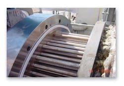
Figure 1. Form-in-place ePTFE gasket tape can effectively seal flanges on large shell-and-tube exchangers.
In addition, custom gasket construction raises the risk of variation in quality and performance. Large pre-cut gaskets also are difficult to ship and store. Moreover, these gaskets add complexity to the installation process, as they often require delicate handling to avoid functional damage. Frequently, cranes are needed to hoist them into place.
Large systems and equipment and their related flanges sometimes are hydro-tested by the original equipment manufacturers using a generic, elastomer gasket type. While this is fine for checking vessel integrity, it often leaves the user plant without clear direction when it comes to gasket selection in actual service.
For actual service, a user should choose gasket materials based on multiple criteria, including: the kind of media being processed, temperatures, flange loading, operation dynamics and installation methods.
Moreover, while elastomer-based materials provide an effective short-term seal for the hydro-test, they frequently can mask hidden imperfections in larger flanges. Once users move to more-traditional gasketing choices for real plant operating conditions, even the slightest flange imperfections quickly can come to light. That’s because metal, polytetrafluoroethylene (PTFE) and other commonly used gasket materials often sacrifice conformability (relative to elastomers) for higher chemical and temperature resistance, and durability.
Due to these layers of complexity, and with few specification guidelines or shared best practices to go on, it’s no wonder that plants often use many different custom-fabricated gaskets. This can result in some surprising situations. For example, one large vessel might have a specific gasket construction that works very well for it. Situated right next to that vessel may be a similar one that relies on a dramatically different gasket construction. In many cases, no one currently in the plant can explain the reason for the disparity, the rationale having been lost over time.
The Current Situation
While each processing facility has its own unique characteristics, we can generalize to a significant degree about common practices regarding gaskets for large equipment flanges.
For large gaskets that are custom-fabricated offsite, first, the critical dimensions are measured and mapped to enable a gasket fabricator to create the specialty size or shape required for the application. The more-sophisticated gasket fabricators archive these dimensions — and have transitioned from cardboard cutouts to digital design files.
Because these gaskets are specialty items, generally only when a plant places an order does the construction process begin. This is why a gasket often requires a lengthy lead time — sometimes as much as four to eight weeks before delivery.
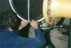
Figure 2. Forming complex gaskets is straightforward — overlapping sections of tape don’t pose a leakage issue.
To cope with this, many processing facilities have learned to order their supplies early. This can create significant challenges and stress on the plant’s procurement and turnaround planners. Typically, storerooms are encouraged to keep multiple extra gaskets for specialty units in inventory “just in case” of a supply pinch or to serve as backups should gaskets get damaged in transit, storage or installation — an all-too-common occurrence with large specialty gaskets.
Visit Your Storeroom
When was the last time you took a look at your plant’s gasket stores and checked out the large gasket situation?
If yours is like many processing facilities, you’ll find a multitude of material types — each selected to accommodate the various plant operations. Maybe some have been procured as the result of “fighting fires” over the years in desperation to seal a finicky unit.
PTFE is a favored gasketing material for chemical service; it comes in wide number of varieties, ranging from 100% pure PTFE (including expanded) to versions filled with glass, barium sulfate, or even ceramics. You’ll likely find a multitude of gasket constructions, too. Some large gaskets are welded together from smaller pieces, some are sandwich constructions with metal for added stability, and others may have a PTFE envelope surrounding components of other materials.
A notably unstandardized application is large gaskets in heat exchangers. Your plant may have a number of unique large gaskets dedicated to a variety of heat exchanger configurations that vary by vessel size and by crossbar placement or number.
Without a doubt, the rationale for procuring each and every one of these products was individually sound and justifiable. However, what you’ve ended up with is a complex mess.
Another key point about the ownership of such a complex collection of large gaskets is that it ties up a significant amount of money you might prefer to use elsewhere.
Changing The Paradigm
Now, a different — and simpler — way to manage large-flange gaskets exists. It offers compelling benefits and savings, from:
• freeing up dollars “held hostage” as inventory in the storeroom;
• allowing instant customization into any shape — while being installed on the flange — regardless of size or configuration;
• eliminating the need for metal for gasket rigidity because the gasket adheres right to the flange surface with no further intervention required;
• using a material that provides broad chemical compatibility;
• enabling a single gasket to seal imperfect or damaged flange surfaces, reduce emissions and improve plant reliability; and
• making the use of cranes for installation unnecessary.
The approach leverages the latest generation of form-in-place gasket tapes. They can replace pre-cut gaskets made of rubber, synthetic fiber, composite materials and PTFE that contains fillers or other additives.
Such gasket tapes take advantage of expanded PTFE (ePTFE), a material that offers almost universal chemical resistance.
In addition, ePTFE boasts enhanced strength and creep (cold flow) resistance under high loads and temperature, making it ideal for industrial flanges.
Also, ePTFE is significantly more conformable than other PTFE-based gasket materials, enabling it to accommodate deviations and imperfections in large flanges.
Furthermore, the use of a gasketing tape, as opposed to a pre-cut gasket, provides maximum flexibility and ease of installation for large gaskets (Figure 1).
Unlike other PTFE gasketing, the microstructure of gasket tapes such as Gore Series 500 results in greater reliability and enhanced operational tightness — even under more extreme operating conditions.
The advantages of ePTFE form-in-place gaskets include:
• elimination of lead time;
• onsite customization;
• quick and easy installation, including on shafts and bundles, vertical flanges and in special configurations;
• easier shipment and storage; and
• reduced inventory requirements.
Forming the gasket requires the overlapping of a section of tape (Figure 2). This has led to a misperception that form-in-place gaskets, because the material isn’t installed as a continuous one-piece unit, may be apt to leak at the overlap. However, third-party testing shows the overlapping material doesn’t cause leaking. In fact, ePTFE gasket tapes actually can deliver more tightness compared to other sealing solutions.
Successes
Such ePTFE gasket tapes already are delivering substantial benefits at plants, as the following two examples illustrate.
A chemical plant required a catalyst changeout every month. This posed a number of challenges:
• The reactor lids were nearly 10 ft in diameter and located three stories off the ground.
• Gaskets were being fabricated offsite and delivered approximately four weeks after they were ordered.
• A crane was needed to hoist the gasket into place. Because the gasket was fragile, the backer board had to remain attached during the procedure.
• On windy days, the gasket behaved like a giant kite, causing additional safety concerns — not to mention frustration for the maintenance crew.
Switching to Series 500 gasket tape dropped product lead time from about a month to mere days. A single maintenance worker could walk the gasket tape package up the unit stairs — no crane was required. An adhesive backer made installation of the gasket tape on the tilted reactor quick and easy.
At another plant, a boiler gasket had to be changed approximately every year due to gasket degradation. This required four working days for two fitters, including two days of production downtime.
Switching to the ePTFE gasket tape enabled replacement to take place during a single work shift. Moreover, the gasket material does not degrade, extending the maintenance cycle to six years. The change saves 46 man-days of maintenance and provides 12 additional production days over the six-year period.
What Causes Sealing Failures?
When a flange won’t seal, the gasket usually gets blamed. However, a research study commissioned by the Pressure Vessel Research Council, Shaker Heights, Ohio, found the root causes to be: improper installation, 26%; damaged flange, 25%; defective gasket, 22%; loose bolts, 15%; and flange misalignment, 12%.
As this highlights, adhering to basic installation and correct bolting practices can avoid many problems. So, it’s important to properly train your installers.
ROB HAYWOOD is a product specialist at W. L. Gore & Associates, Elkton, Md.
E-mail him at [email protected].


