Many chemical plants rely on reciprocating compressors. These units, also known as piston-type compressors, can generate high head independent of the gas density. They currently are the only compressors available for producing pressures above 1,000 bar. They particularly suit services with relatively low capacity and relatively high differential pressure.
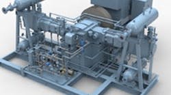
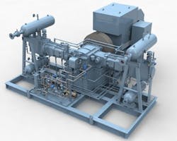
Figure 1. This medium-size two-cylinder unit has suction pulsation bottles installed above the cylinders and discharge ones below. Source: Cobey
[Related: Correctly Commission Rotating Equipment]
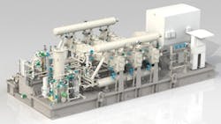
Dry (oil-free) seal components may not last as long as lubricated sliding components because they might not stand up as well to friction and wear at sliding and contacting surfaces. However, oil-free operation may provide better overall reliability for an entire chemical processing unit, if the compressor uses suitable oil-free components (particular sealing materials) and has proven itself in comparable services.For large, high-speed or high-pressure machines, lubricated cylinder technology may remain the first choice. A lubricated cylinder in a low-speed (around 300–350 rpm) machine may be the best option for large (>1.5 MW) or high-pressure (say, >50 barg) services, if there's no process requirement for zero oil carryover.Traditionally, low-speed (around 330 rpm) reciprocating compressors with lubricated cylinders promised the highest reliability. However, starting about 20 years ago, many vendors began challenging the lubricated-cylinder low-speed mantra for small- and medium-size machines. Now, oil-free (non-lubricated) technology is well established. Speed remains a critical issue for both oil-free and lubricated units. High speed ranges could result in relatively small compressors with cost, weight and space benefits. However, machine reliability, particularly for contacting and sliding surfaces, could decrease. So, speed selection demands care. The optimum piston speed usually falls in 3–4.5 m/s range. Large- and medium-size machines typically operate at around 300–350 rpm, while small compressors (say, <250 kW) may run at up to 600 rpm. Oil-free compressors generally have lower speed limits than lubricated ones.Figure 2. Six-cylinder compressor uses two long horizontal pulsation vessels, each connected to three cylinders. Source: Cobey
[Related: Rethink Options for Large Drivers]
Suction drum and coolant system. Liquids should never form inside a reciprocating compressor cylinder. Liquid contributes to poor reliability, can cause high impact velocities, lead to stressing of cylinder valve moving elements (slugging) and reduce sealing effectiveness. Therefore, always provide an adequately sized suction drum with a drain system. Sometimes the suction drum comes as a part of the pulsation control system. However, a separate vertical-type suction drum (separate from the horizontal-type suction pulsation vessel) near the compressor package generally is the best option.
The primary purpose of the cooling system is to avoid hot spots within the cylinder and the rod packing. Cooling is even more critical for oil-free compressors. Their vulnerable dry sealing elements rely on the cooling system to prevent frictional heat, sliding wear and operational hot spots. So, always provide ample margins for cooling water flows. Closely monitor the operation and temperatures of the cylinder cooling system. Coolant inlet temperature should exceed the inlet gas temperature by 7°C to 15°C and should be closely controlled within minimum and maximum limits; a margin of ≤5°C can be problematic. Exotic gases or operations near critical areas demand more attention to coolant temperature control. Carefully review the thermodynamic model to ensure liquid can't form and cooling system performance is properly set for the cylinder(s) and other critical points such as rod packing.
PULSATION CONTROL
Often people at process plants complain about the pulsation of reciprocating compressors. The trend today is to rely on techniques that dissipate less energy than special dampening solutions, such as orifices, to decrease pulsation levels. Vertical-type suction pulsation vessels have been used on large reciprocating compressors for years but prompt many pulsation and operational problems. In particular, the relatively long connecting piping line between the compressor and the vertical pulsation vessel (which should stand near the machine but usually can't be placed any closer than 1 m to 2 m or more away) could be a source of severe pulsation and a good candidate for detrimental resonances. Even for mammoth-size compressor installations that would require large horizontal suction pulsation vessels and massive supports on top of the compressor cylinder, the horizontal layout is a much better choice than a vertical suction vessel with a relatively long connecting pipe spool and the resulting pulsation resonances.
When using orifices for pulsation dampening, it's best to place them at the nozzle-end inside the vessel. If conditions change much from the design basis, you should replace the orifices with ones appropriate for the new conditions. This can require cutting and rewelding of thick pulsation vessels at the site — an extremely difficult and risky job.
To avoid the risks and hassles posed by vertical vessels and orifices, always opt for horizontal pulsation vessels. Older designs use a combined pulsation vessel — the large six-cylinder compressor shown in Figure 2 has two such vessels, each connected to three cylinders — to ease installation. However, it's better to have horizontal suction and discharge pulsation vessels strategically installed near each cylinder. Carefully select the distance between the horizontal pulsation vessel nozzle and the cylinder nozzle. The optimum distance should guarantee trouble-free access to the valves, unloaders and other cylinder accessories (without removal of the pulsation vessels). At the same time, the distance shouldn't be long enough to cause any resonance with generated pulsation (and its harmonics) because unsuppressed pulsation harmonics at the immediate discharge of the reciprocating compressor (between the machine and the pulsation vessel) could prompt problems. As an indication, around 0.4–0.7 m could be a good distance to select for medium-size reciprocating compressors, considering access, valve maintenance and pulsation.
AMIN ALMASI is a rotating equipment consultant based in Brisbane, Australia. E-mail him at [email protected]


