1312-heat-exchanger-errors

Head Off Heat Exchanger Errors

Dec. 16, 2013
Selecting the most-appropriate heads for a shell-and-tube unit is crucial.

Most process shell-and-tube heat exchangers are manufactured to Tubular Exchanger Manufacturers Association (TEMA) standards. These standards include a three-letter designation of the exchanger type that specifies overall mechanical layout in the form: front-end head, shell type and rear-end head.
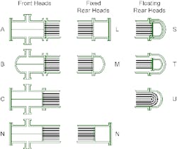
TYPES OF HEADS

Figure 1. The Tubular Exchanger Manufacturers Association provides specific designations for heads.

Figure 1 shows the most common front-head-end and rear-head-end designations. It illustrates a two-pass exchanger configuration on the tube side. The front-end head gets the tube-side fluid into the exchanger. Multiple tube-pass exchangers include a channel to separate the flow in each pass. Table 1 provides rough guidelines for application of the common front-end heads.A-type heads allow for easy access directly to the tube sheet without having to disconnect the head from the piping. This makes tube cleaning relatively straightforward. B-type heads also allow access to the tube sheet for cleaning but require removing the head from the piping. B-type heads eliminate one body flange ring and, so, are less expensive.C-type heads have the tube sheet integral with the head, which usually is welded to the tube sheet. However, in lower-pressure and smaller-diameter applications, the tube sheet may be welded inside a flanged pipe section. C-type heads most often are used with hazardous tube-side services that still require cleaning. The welding eliminates one area where leaks might occur.
Front-End-Head Guidelines

Table 1: Each type of head suits a different specific service.

N-type heads have the head, tube sheet and shell all welded together. They typically are selected when both the tube and shell sides contain hazardous materials. They also may be used in very clean shell-side services to save money. The design must allow for thermal expansion. Most exchangers will require expansion joints in the shell to accommodate thermal stresses due to different temperatures on each side. Without thermal expansion joints, the exchangers tend to leak at the tube sheet.The rear head can be either fixed or floating. The fixed-head types have similar configurations to front-end heads: the L-type resembles the A-type front-end head, the M-type the B-type front-end head, and the N-type the front-end N-type. They all have the same benefits and constraints as the corresponding front-end heads.Floating heads have completely different configurations. The floating head disconnects the rear end of the tubes from the shell. This allows for differential thermal expansion between the shell and tubes without need for expansion joints. Table 2 highlights particularly suitable uses for the most common rear-end-head types: the S, T and U. The S-type and T-type use an internal head; both allow for the simplest tube replacement.
Floating-Rear-End-Head Guidelines

Table 2: The head variants best handle certain kinds of applications.

The S-type has a two-piece backing ring that flanges to the internal head to keep the shell fluid and the tube fluid separated. The backing ring normally is larger than the inside diameter of the shell. This configuration enables tubes to be relatively close to the shell wall. It does require taking the rear head off the exchanger to pull the tube bundle out.The T-type doesn't use a backing ring. The internal flange for the rear head is smaller than the shell diameter. The tube bundle can be removed for cleaning the shell side without needing to open the rear end of the exchanger. T-type rear heads routinely are used when the shell-side fluid is fouling. Due to the clearance required for the rear head, T-type exchangers are larger for the same area or have less area for the same shell than S-type ones.U-type exchangers completely dispense with the internal tube sheet — enabling the tubes to be placed closer to the shell wall. This minimizes shell size for new exchangers or provides the maximum area for an existing shell. The U-tube configuration allows each tube to expand or contract independently. For multiple-pass exchangers, this may be important because tube passes may significantly differ in temperature. Except for the outside tubes, tubes can't be replaced easily. Tube leaks normally are dealt with by plugging a tube.Each of these configurations fills specific niches. Choosing the right configuration is the starting point to a cost-effective and usable shell-and-tube exchanger. For tips about allocating fluids in tubular exchangers, see: "Pick the Right Side."

ANDREW SLOLEY is a Chemical Processing contributing editor. You can email him at [email protected].

Sponsored Recommendations

Connect with an Expert!

Our measurement instrumentation experts are available for real-time conversations.

Maximize Green Hydrogen Production with Advanced Instrumentation

Discover the secrets to achieving maximum production output, ensuring safety, and optimizing profitability through advanced PEM electrolysis.

5 Ways to Improve Green Hydrogen Production Using Measurement Technologies

Watch our video to learn how measurement solutions can help solve green hydrogen production challenges today!

How to Solve Green Hydrogen Challenges with Measurement Technologies

Learn How Emerson's Measurement Technologies Tackle Renewable Hydrogen Challenges with Michael Machuca.