Don't Underestimate Overfilling's Risks

Loss of level control has contributed to three significant industrial incidents:
- In Australia, the Esso Longford explosion in September 1998 resulted in two fatalities, eight injuries, and A$1.3 billion (more than U.S. $ 1 billion) in losses [1];
- In the U.S., the BP Texas City explosion in March 2005 caused 15 fatalities and more than 170 injuries, profoundly affected facility production for months afterwards, and incurred losses exceeding $1.6 billion on BP [2]; and
- In the U.K., the Buncefield explosion in December 2005 injured 43 people, devastated the Hertfordshire Oil Storage Terminal, and led to total losses of as much as ₤1 billion (about $1.5 billion) [3, 4].
These incidents involved different industries located in different countries. Each uniquely propagated, arriving at its final outcome through different mechanisms. Yet, all suffered the same process deviation of high level and all resulted in devastating consequences. This article discusses significant factors contributing to these incidents and provides a simple seven-step solution for overfill protection.
Key Causes
Five factors contribute to overfill events:
Lack of hazard recognition. Level usually has little significance to plant output or product quality. "Normal" operating level often isn't well defined or tightly controlled. Absolute level frequently varies over a large range but doesn't come close to threatening equipment integrity. In tank farms, operating level is simply inventory to be managed.
High level often isn't a hazard itself. Instead, the danger comes from too much mass or volume. Some overfills challenge the tank or vessel where the level is accumulating, causing overpressure or collapse when retained mass exceeds equipment structural-design limits. Many overfills result in loss of containment when liquid passes to downstream equipment that isn't designed to receive it.
Overfill hazards vary depending on the type of vessel and associated upstream and downstream equipment. It's rarely effective to allow a high level event to propagate and to depend on downstream process variables being fast enough to prevent equipment damage. For example, high level in a knockout drum requires immediate response to avoid compressor damage; you can't wait until high compressor vibration is detected.
Underestimating the likelihood of overfill. Level seems so simple to detect that anyone should be able to recognize overfilling and respond in a timely manner. Unfortunately, operators rarely can directly see high level. It's just one of many process variables on the display. Worse yet, level often doesn't affect unit operation or cause any other significant process-variable disturbance — until safe fill level is exceeded and, suddenly, mechanical integrity of the vessel or interconnected equipment is threatened.
High level may have different causes in each mode of operation, e.g., start-up, normal or upset conditions. Start-up may require accumulation of level, so the outlet control valve initially is in manual operation and closed until normal operating level is reached. Level may vary over a large range during normal operation. During upsets, operators may run vessels at higher-than-normal levels, using available capacity to dampen impacts on upstream or downstream equipment.
Some hazard-analysis teams erroneously believe that overfill isn't a credible event because it generally takes minutes or hours rather than seconds to fill a vessel. Some events propagate slowly, such as rise of level in a product storage tank, while others occur quickly through a random event, such as a process upset sending excess liquid to a knockout drum for a compressor. The slower the event, the greater the tendency to believe the operator can adequately address it; likewise, the more sporadic the event, the greater the tendency to believe it won't last long enough to cause overfill. Believing high level isn't credible is especially attractive when the existing design doesn't provide for a high level alarm or trip.
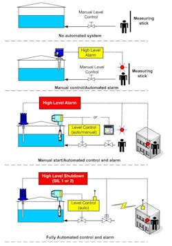
Estimating the likelihood of overfill is complicated by the combination of manual and automated control that's necessary as equipment is started up and operated. Figure 1 shows the range of automation commonly found in tank farms and terminals. The degree of automation generally relates to the expected rate of level rise and operator workload. Automated control and safety systems typically are added when control changes must be made too often to be continuously managed by the operator or when work complexity has increased to where the expected human error rate is no longer acceptable.
It's important to specify the safe fill limit and explain in operating procedures the consequence of exceeding it. Without clearly stated limits and consequences, the operator may not adequately monitor level, especially during intense work periods. Overfill is a credible event; it takes good operating procedures to reduce its likelihood.
Excessive reliance on the operator. The length of time required to reach overfill encourages a tendency to "blame the operator." In many applications an operator does have adequate time to control level within acceptable tolerance — but human error always is possible. Workload and piping network complexity decrease the operator's ability to reliably control level and maintain process safety. Debottlenecking and expansions to increase production often raise operator workload and erode time available to respond to abnormal events. In some cases available time has been reduced to where manual response is no longer effective and automated overfill protection must be implemented.
Don't neglect hazards to operators posed by manual actions such as draining knockout drums. Local response generally moves the operator into the hazard zone, increasing risk to that individual. Consequently, the design must provide sufficient time for the operator to take action and means to verify the intended process response. Further, there should be time to evacuate the area if the action doesn't work as expected. When fast response is required, consider drills to allow the operator to practice the response and to verify the time required to detect and respond. These drills can identify issues with the design, installation and labeling, as well as with procedures and training.
Automated controls are often added to increase operating efficiency and reliability. They also should be provided to reduce reliance on operator response near a hazardous event. For significant hazardous events, automated trips ensure continuous protection even when an operator is focused on other duties. A safety instrumented system (SIS) detects high level and prevents filling beyond the safe fill limit. The SIS can be a simple hardwired system using an independent level sensor (e.g., switch or transmitter) to spot high level and an independent final element (e.g., motor control circuit or block valve) to terminate or divert feed. The SIS is automatically initiated at a setpoint that allows sufficient time for the action to be completed safely. Risk analysis determines the safety integrity level (SIL) required to provide adequate protection — usually SIL 1 or SIL 2.
No defined safe fill limit. In many applications the entire level range from empty to postulated failure point isn't displayed. Instead, the measurement device only covers the expected operating range. While this provides the most accurate measurement across the operating range, it unfortunately leaves the operator with no indication of level when it rises above that range.
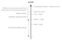
The design basis should clearly establish the safe fill limit, based on an understanding of postulated failure level, analytical capability of instrumentation used for measurement, fill rate, and time required to achieve a safe state. The safe fill limit should ensure that action can be completed prior to reaching the postulated failure level. It should account for expected measurement drift in the process and environmental conditions.
Figure 2 shows the transition of level from normal operating range to postulated failure point. Providing an alert can support level control; its setpoint should allow enough time for the operator to respond to prevent the level from reaching the safety alarm or trip setpoints. The safety alarm should give the operator enough time to bring level back under control or to take equipment to a safe state.
The offset between trip setpoint and safe fill limit is the design safety margin. When an alarm also is implemented, its setpoint should be far enough below the trip setpoint to allow the operator sufficient time to take the process to a safe state prior to trip initiation. Otherwise the alarm loses merit as a protection layer and simply serves as a pre-trip notification.
Inadequate mechanical integrity. Many technologies are available for level measurement and detection, from simple float-type discrete switches to complex guided-wave radar transmitters. Each technology has characteristics that make it the right choice for a particular application [5]. There are no bad level devices, only technology misapplications, improper installations and inadequate mechanical integrity programs. A properly maintained level switch can provide years of cost-effective satisfactory service. On the other hand, neglect can cause the most expensive device to fail.
For most safety applications the main considerations for equipment selection are required accuracy, process operating mode, operating environment, historical equipment performance, and ease of maintenance and testing.
No matter the technology selected, it's crucial to maintain mechanical integrity of equipment over its life. Functionality is demonstrated by forcing the sensor to "see the process variable" and to generate the correct signal at the specified setpoint. Testing must prove that equipment can operate as required to prevent overfill. Although diagnostics can detect many types of failures, a proof test is necessary to demonstrate operation at the required setpoint.
Some companies only allow transmitters in safety services, banning direct-mounted switches due to their lack of continuous signal. For columns and storage tanks, the safe fill limit usually is significantly outside normal operating level, resulting in high level alarm or trip sensors being at a very low output for long periods of time. In such a circumstance, a discrete sensor like a switch may be a better choice. Consequently, it's an acceptable practice to implement an automated control system that uses an analog measurement covering expected normal operating range and a level switch to initiate feed shutdown.
You can implement a high level alarm and trip with separate level switches at appropriate points on the vessel or with a transmitter that covers both setpoints. Although transmitters may not improve diagnostics in services that don't normally have level, they do provide the ability to monitor over a chosen range and to alarm at various points in the range.
The Solution
You can easily prevent catastrophic overfills. When overfill can lead to a fatality, follow these seven simple steps to provide proper protection:
1. Acknowledge that overfill of any vessel is credible regardless of the time required to overfill.
2. Identify each high level hazard and address the risk in the unit where it's caused rather than allowing it to propagate to downstream equipment.
3. Determine safe fill limit based on mechanical limits of the process or vessel, measurement error, maximum fill rate and time required to complete action that stops filling.
4. When operator response can be effective, provide an independent high level alarm at a setpoint that gives the operator sufficient time to top accumulation of level before the trip setpoint is reached.
5. When an overfill leads to release of highly hazardous chemicals or to significant equipment damage, design and implement an automated overfill-protection system.
6. Determine the technology most appropriate for detecting level during abnormal operation. This technology may differ from the one applied for level control or custody transfer.
7. Finally, provide means to fully proof test any manual or automated overfill-protection system to demonstrate its ability to detect level at the specified setpoint and take action in a timely manner.
Angela E. Summers, Ph.D., is president of SIS-TECH Solutions, LP, Houston. E-mail her at [email protected].
REFERENCES
1. "1998 Esso Longford Gas Explosion," Wikipedia, http://en.wikipedia.org/wiki/1998_Esso_Longford_gas_explosion.
2. "Texas City Refinery (BP)," Wikipedia, http://en.wikipedia.org/wiki/Texas_City_Refinery_(BP).
3. "The Buncefield Incident 11 December 2005: The Final Report of the Major Incident Investigation Board," Buncefield Major Incident Investigation Board, London (2008). Available online at www.buncefieldinvestigation.gov.uk/reports/index.htm#final
4. "Buncefield blast could cost ₤1 billion," British Broadcasting Corp., London (December 11, 2008). Available online at http://news.bbc.co.uk/2/hi/uk_news/england/7777539.stm.
5. Boyes, W., "First the Application, Then the Product," p. 45, Control (Feb. 2007). Available online at http://www.controlglobal.com/articles/2007/022.html.