Click Image To Enlarge
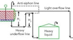
Figure 1 -- Liquid seal loop system: This piping
arrangement obviates level control instrumentation.
Click on illustration for a larger image.
|
The difference between the underflow seal leg height (H
1) and the overflow height (H
2) creates a static pressure that must be balanced by the liquid column in the drum. Because the H
2-height column contains all heavy liquid and, thus, differs in density from the average density in the H
1-height column, the interface between the heavy phase and light phase varies with the density difference: ΔH = H
1 – H
2H
3 = ΔH /[1 – (ρlight/ρheavy)] The H
1 and H
2 heights must use a common reference line. It needn’t be at any specific level but must be low enough to be below the light-phase/heavy-phase interface. Figure 1, while not to scale, roughly shows the expected height ratios for a specific gravity of 1.0 for the heavy phase and 0.72 for the light phase. We can easily see that the smaller the density difference between the light phase and heavy phase the greater the multiplier effect — that is, the larger H
3 becomes for a fixed height difference in the external piping. The use of the level seal becomes more powerful as the density difference decreases. Closer inspection of Figure 1 reveals some other critical items. The heavy-phase overflow line requires an anti-siphon line (siphon breaker) to prevent pulling the heavy phase out of the drum. Vessel pressure also affects the liquid levels. Figure 1 shows the separator vessel and both tanks with open vents to atmosphere. If all the vessels instead tie into a vent system, it should be a common system with no pressure drop imposed by vent flows. The separator system is sensitive to pressure drops. Even a relatively small liquid-side pressure drop can radically change the liquid interface level. The system works best with oversized lines out of the drum. To modify the estimate of interface level to account for pressure drops, you must add a friction loss term: ΔH
friction = ΔP
light - ΔP
heavyH
3 = (ΔH
static + ΔH
friction)/[1- (ρlight/ρheavy)] The pressure drops through the light-phase and heavy-phase outlet systems are in height of the respective liquid. The static head difference remains the difference between H
1 and H
2. Of course, to get the desired elevation you also must be able to accurately predict process densities. If process densities vary, check the levels against residence time requirements for all relevant density combinations of the two fluids. Once the system is built, you only can adjust the level by varying either the height of the piping or the pressure drop in the piping. You can change the height of the underflow piping by using a flanged spool piece that can be rotated on its bolt holes to alter the H
2 height. You can adjust pressure drop in the outlet piping either with a restriction orifice between flanges or via a valve or variable obstruction in one of the lines. Usually the obstruction is placed in the heavy liquid line. The advantage of a valve or variable obstruction is that it can change the liquid interface without having to shut down and empty the equipment. Many plant requirements and problems can be solved with clever piping configurations. Don’t automatically jump to the high-tech solution of more instrumentation, interlocks or complex equipment. First look at the fundamentals of what you want and search for simple solutions.
Andrew Sloley is a Chemical Processing
Contributing Editor. You can e-mail him at [email protected].


