Mechanical Seals: Gas Up Your Sealing Knowledge

As users become more familiar with gas seal technology and its advantages, gas seals are being applied to a wider variety of applications and equipment than ever before. Its common to see gas seals in agitators and other equipment where product contamination is an issue, such as units in the pharmaceutical industry. As gas seals become more common, its important that users understand the differences between them and liquid lubricated seals. First, lets start with the basics.
Mechanical seals consist of two seal rings mated together to create a seal at their interface. One seal ring rotates with the shaft and the other is stationary. The mating faces of these seal rings typically require lubrication from either the process fluid, a barrier fluid or, in the case of gas seals, nitrogen gas is used to separate the faces.
Compressible fluid
A typical gas seal design will use hydrodynamic lift-off to separate the rotary and stationary seal faces. Spiral grooves in the rotary seal face collect the gas. As the seal rotates, gas is compressed towards the end of the groove creating an opening pressure. This pressure exerts an opening force greater than closing force, separating the seal faces. This slight separation allows the gas to flow across the seal faces. Thus, the seal faces ride on a pressurized, gaseous fluid film (Figure 1).
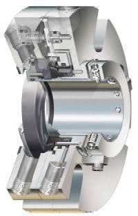
Figure 1. A cutaway drawing of a compact gas seal.
Inexpensive and inert nitrogen gas is typically used with gas seals and gas consumption is a function of differential pressure between the process and regulated gas supply pressure.
Liquid lubrication
Single liquid lubricated seals rely on the process fluid in the equipment to lubricate the seal faces of a mechanical seal. Dual mechanical seals can use an external pressurized fluid to lubricate the seal faces. In chemical plants, seal barrier fluid tanks are used to maintain a constant supply of pressurized liquid.
The faces of liquid lubricated seals operate in a mixed lubrication environment where face loading is only partially supported by the sealed liquid between the faces as rotary-to-stationary face contact also exists during equipment operation. The liquid present serves only to minimize face loading on the seal faces. Therefore, liquid lubricated seals generate heat at the seal faces due to rotary-to-stationary face contact during equipment operation. Liquid lubricated seals are very dependent on the tribological characteristics of the fluid, seal face design and materials at the operating pressures and temperatures of the equipment.
Select the right seal
Although the configuration of the seal is often dictated by regulatory requirements, the type of seal is left to the engineer. So, the question is: liquid or gas? Gas seals are no different than any other mechanical seal in that regard. Gas seals excel in many applications while in others there are other types of seals that exhibit better performance. To understand the application parameters that are ideal for gas seals, fluid characteristics, equipment operation and operating procedures need to be analyzed.
The ideal fluid to seal in process equipment is cool, lubricating, environmentally friendly and free of particulates. However, many chemical plants are dealing with difficult-to-seal fluids that are hot, polymerizing and operating at low viscosities. Some fluids operate close to their vaporization point and additional heat may cause a phase change. Gas seals are increasingly being used to seal a wide variety of applications in plants. Gas seals are replacing liquid-lubricated dual seals and, magnetic and canned pumps. They are replacing single seals as plants look to increase the reliability of their equipment.
Considerations for single seals
To better understand gas seals its important to understand the limitations of other sealing designs. Single seals use the process fluid. When this fluid is hot, corrosive, abrasive, and viscous, in other words, when the fluid is a poor lubricant, a long life may not be anticipated.
Beyond these concerns there are operation and maintenance concerns. Intermittent dry running, intolerable leakage, inadequate or incompetent maintenance, and the remoteness of the location are all issues in selecting a seal. In many processes, especially batch processes, pumps are often inadvertently run dry, which will cause seal failure due to excessive frictional heat.
Even with process fluid present, single seals will conduct heat developed at the seal face by friction directly to the fluid. The temperature of the fluid will rise and the viscosity will decrease. This reduces the lubrication of the process fluid and, in turn, the seals service life. Other physical properties of the process fluid can affect seal life. Some fluids will polymerize with heat. All single seals have a process fluid/air interface that occurs at the seal faces; this is a concern for fluids that form polymers. Solutions with dissolved solids such as sodium hydroxide, caustic, will precipitate at high rates with increasing temperatures. Of course, fugitive emissions also can be a concern with single seals.
Dual seals
Dual seals are next in the hierarchy of mechanical seal types. Dual seals can operate on an externally applied barrier fluid and eliminate the need for process fluid. A seal is sometimes maintained by a barrier fluid tank. This vessel is pressurized by a second, clean fluid, often water. While the system receives regulated pressure, the liquid level in this system is maintained by operators and requires periodic maintenance. If the liquid level isnt maintained both the inboard and outboard set of seal faces will operate dry, causing excessive frictional heat and premature failure.
The barrier fluid selected should be non-hazardous and compatible with the process. Often, the barrier fluid itself can be problematic, as it may not have ideal lubricating properties.
Magnetic and canned pumps
Magnetic and canned pumps are used to attempt to alleviate the issues with wet lubricated single and dual seals. However, plants have seen that a new set of concerns arises with the use of this equipment. Maintenance on this equipment is highly specialized and usually involves using outside repair shops. The bearings supporting the radial and axial thrust in these pumps are lubricated by the process fluid, exacerbating the lubricating needs found in single seals. Other problems including a poor tolerance for intermittent operation, sensitivity for variations in fluid properties or condition, have limited their use.
What can gas seals offer?
Gas seals operate on a gas fluid film and dont generate significant frictional heat. The process fluid isnt the lubricant as with single seals. Unlike dual seals that require compatible barrier fluid, gas seals often use inert nitrogen that isnt a compatibility concern and isnt generally hazardous. Barrier fluid tank maintenance costs, specialized refilling procedures and their impact on reliability are eliminated with gas seals.
Gas seals can be easily applied to standard chemical process equipment such as centrifugal pumps and mixers unlike magnetic and canned driver technology. Gas seals are now available in compact cartridge designs allowing existing equipment to easily gain the advantages of gas sealing (Figure 2). Specialized maintenance procedures do not need to be established and operators do not need to refill pressure tanks.
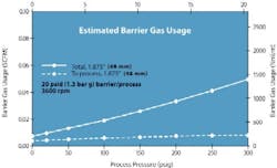
Figure 2. Even at high pressures (above 150 psig), the make-up gas requirements are small. (Click to enlarge.)
Unique concerns for gas seals
As with all equipment, gas seals do pose a new set of questions. Most gas seals operate using hydrodynamic lift-off for seal face. Separation requires a minimum circumferential speed, which is a function of both the equipment RPM and shaft diameter. Circumferential speeds of 250 ft /minute (1.3 m/s) and higher are typically required in standard gas seal designs. However, special gas seal designs are available for slow speed equipment such as mixers.
Gas seals are lightly loaded, axial face seals; theyre more sensitive to loading changes than liquid seals. Face loading is accomplished by both hydraulic forces and spring forces. Fluids that are film-building, such as paint, can limit the movement of mechanical seals. Slurries, containing more than 5% solids, also present problems. These fluid properties can be managed by using a seal flush and/or anti-particulate stuffing box. Process fluids that chemically attack the o-rings in a mechanical seal may increase seal drag, decreasing gas seal performance. While gas bellow seals can be used to eliminate o-ring sensitivity, they cannot easily attenuate vibration at the seal faces introducing another set of concerns.
Fluids with high freezing points may solidify when ambient temperature gas is introduced into the equipment (auto-refrigeration). Gas seals are more sensitive to high viscosity process fluids. Evaluate process viscosities at normal operating temperature and cold start-up. If these are concerns, the supply gas lines can be heat-traced.
Design considerations
For a successful gas seal installation, clean, dry barrier gas should be supplied to the gas seal. Pressure must be regulated within two limits: above the maximum stuffing box pressure and below the maximum system design pressure. Proper pressure regulation ensures that the seal faces are lubricated with a gas barrier, while maintaining a clean environment between the faces.
Pressurized gas seal should be from a reliable source and set at a pressure thats regulated to at least 15 psig (1 Bar) above the maximum sealing pressure in the equipment. While older designs use large control panels to regulate pressure at maximum pressure levels, newer designs are available that actively regulate gas pressure with respect to changing stuffing box pressure to ensure low gas consumption and maximize reliability. Typical gas usage is shown in Figure 3 and is often well below 1.0 SCFH of consumption.
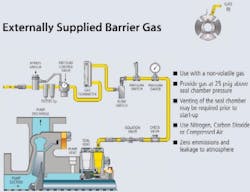
Figure 3. Plan 74 isolates process fluid, thereby preventing emissions.
The compressed gas should be dry and filtered to ensure reliable operation. Design of the gas panel should allow for routine filter maintenance with minimum intrusion into production. A coarse and fine filter system is the accepted practice as it allows easy filtration down to two microns (Figure 4). Upon seal installation, blow out the gas supply lines downstream from the filter system to eliminate any tramp metal in the lines.
Figure 4. Options are shown for venting gas that may accumulate during downtime.
Managing gas entrainment
Seals will ingest small amounts of compressed gas during operation. Barrier gas will migrate past the inboard seal faces into a process system by design. Unfortunately, seals are often continuously pressurized. During a shutdown gas flows into the piping system. Unless this gas is vented properly, a condition may occur where the amount of gas is in excess of gas entrainment capability of the pump, process piping, or system design. As a result, the pump can become vapor locked or can experience severe cavitation. The solution is common sense. Vent the excess gas to a lower pressure area than that of the pump stuffing box, making certain to by-pass the inlet piping to the pump.
If all possible causes are exhausted, and the source appears to be inert barrier gas (gas entrainment) from the gas seal, a bleed line will have to be installed. System design and operating pressures will dictate the optimum destination for bleed off. Ideally, a small vent line (1/2 in. min) will typically be connected from the seal gland or the equipment stuffing box connection to one of the following:
- To the top of the suction tank; or
- To the final delivery point of the process fluid if it is at a lower pressure than the pump stuffing box.
In the event a bleed off line isnt installed, excess gas must be bled off the pump discharge (upstream of the discharge check valve) to a lower pressure location prior to pump start-up. The gas has the tendency to accumulate at the highest point in the system. Provided a bleed valve is installed, the gas can be bled through the bleed valve and shut off when fluid flow is evident. The pump can be started after bleeding is complete. The vent, when appropriate, may be used as a continuous vent or for recirculation.
Where a spare pump is on standby and under process pressure the barrier gas has the potential of pressurizing the spare pump. The amount of gas may exceed the pump capability. The same venting procedure, as above, should be followed.
Newer designs automatically track process pressure and maintain the optimum pressure differential between barrier gas pressure and stuffing box pressure which minimizes gas ingestion. Older designs have their gas set to handle maximum or worst case pressure, which at shutdown increases the likelihood of gas entrainment.
Success stories
With gas seals being more compact and easier to use, more end-users are experiencing the positive benefits only gas seals can provide. Recently, a plant switched to a gas seal to minimize the overheating seen in a high pressure, bellows dual seal. The high pressure of the application produced a lot of seal face friction. At another plant, eight pumps were installed so they could have two in operation at any one time; the process fluid is a thermally-sensitive material that polymerized, causing the liquid seals to fail. A gas seal eliminated the hazards associated with of barrier fluid leakage.
Operators are enjoying the maintenance-free aspect of gas seals versus a dual-seal barrier fluid tank system. Recently a plant easily switched to gas seals to meet emissions requirements on light VOCs rather then adopt new dual seals and barrier fluid support systems which were the conventional choice in the past. A propylene booster pump had a single seal. The pump was a chronic poor performer due to the combination of low viscosity and high pressure. A change to a dual seal would require a high pressure, cooled barrier fluid system using synthetic oil. A gas seal was installed instead and has been operating for over a year with no cooling and problem-free. As users become increasingly familiar with the benefits of gas seals and proper application and selection, gas seals will continue to grow as the most efficient sealing device choice.
Scott Boyson is the global business development manager for Chesterton in Wakefield, Mass.; e-mail him at [email protected].