
Mixing should be a process operation, not a mechanical problem. Yet, some plants push a mixer beyond the capability of its mechanical design and then get themselves into trouble. While most mixers can provide a long service life — for instance, some are still operating after more than 30 years — mechanical problems can shorten life or even break parts. Often, the processing capabilities of the mixer fail before the equipment does, but poor processing can cause mechanical problems.
Usually, equipment manufacturers know the limits of their equipment and design to specified conditions. However, over the life of a mixer, process requirements and conditions may change from those specified for design. So, here, we will explore some of the mechanical problems that may befall mixing equipment.
Most everyone appreciates the danger of overloading a mixer, usually by trying to mix a material that is more viscous than the mixer can handle. Actually, many mixers are designed to cope with a wide range of materials and have considerable overload capabilities. Some portable mixers and high-speed dispersers can handle very high viscosities without overloading. Such mixers only may draw less than 10% of the motor power when operated in water. However, other mixers are designed for 85% or 90% of motor capacity and so are less tolerant of upset conditions. While high viscosity is an obvious load factor in mixing, fluid density has a direct effect on the motor load in turbulent conditions. A high density fluid, such as a mineral slurry, can overload a motor that is not designed for process conditions. In any case, gear reducers, shafts, impeller blades and other basic components should be chosen to match the maximum motor load. Still process overloads can occur and may damage the motor or shorten the life of other components.
Mechanical failures
A mixer component, such as a shaft, shaft seal, impeller blade or gear reducer, may fail for several reasons. Differences between actual process conditions and original design criteria often can cause problems. In other cases, installation shortcomings can contribute to equipment failures.
The “wetted” parts of the mixer must be designed to handle mechanical loads, process conditions and potential vibrations. Most mechanical loads come from an interaction between the mixer and the fluid (Figure 1). Obviously, a force is necessary to rotate the impeller. That force is represented by a torque load transmitted by the shaft from the drive to the impeller. Besides the fluid forces that resist the rotating impeller, moving fluid creates random hydraulic forces that act perpendicularly to the shaft.
These forces create a bending moment on the shaft. A typical cantilevered shaft, which is supported only by the mixer drive, can experience significant bending loads. So, selection of shaft diameter requires consideration of both the torque and bending loads.
Torque is easily calculated from the basic relationship of power divided by speed, with an appropriate conversion factor for units:
TQ = 63,025 Pmotor/N (1)
where TQ is torque, in-lbf; Pmotor is motor power, hp; and N is rotational speed, rpm.
Hydraulic loads are based on empirical relationships. An expression for the bending load on a mixer shaft with a single impeller is:
M = 19,000 PmotorLfH/ND (2)
where M is the bending moment, in-lbf; L is the “shaft length to support,” in; fH is the hydraulic load factor; and D is the impeller diameter, in. The “shaft length to support” may exceed the shaft length inside the tank because the nearest support bearing may be in the drive or seal above the tank mounting or flange. Multiple impellers require separate bending-load calculations for each, using the fraction of the motor power at each impeller and at the appropriate shaft length, and then summing of the individual bending loads.
The hydraulic load factor may surpass 1.0 for cases where loads fluctuate, as in gas dispersion or boiling systems (fH = 2.0 to 3.0), or where extreme external loads may occur, as with impacting large clumps of solids (fH = 3.0 to 7.0). The severe load most often overlooked is prolonged operation at the liquid level, as when filling or emptying the tank. Operation near the liquid level may result in a significant hydraulic load factor (fH = 2.0 to 3.5), depending upon impeller type and mixing intensity.
Once the torque and bending loads have been estimated, basic calculations can be made for the shear and tensile stresses in the mixer shaft.
The expression for shear stress is:
σs = 16(TQ2 + M2)½/πd3 (3)
where σs is shear stress, psi; and d is shaft diameter, in.
A typical allowable shear stress for carbon and stainless steels is 6,000 psi. This stress level takes into account the effects of fluctuating mixing forces that could result in a fatigue failure.
A similar expression for tensile stress is:
σt = 16(M + (TQ2 + M2)½)/πd3 (4)
where σt is tensile stength, psi.
A reasonable allowable tensile stress level for steels is 10,000 psi. Higher-than-allowable stress levels may lead to a fatigue failure of the mixer shaft. Other factors, such as welds or steps in the shaft, may cause stress risers that may increase local stresses, which, in turn, could result in failures. Fluctuating loads also act on the impeller blades and may cause other component failures.
The vertical forces on the mixer, such as weight, pressure and thrust, have little impact on the shaft design but may affect mixer mounting. Axial flow impellers create some axial thrust, enough to occasionally lift an impeller off shaft mounts.
Bearings on the output shaft of the mixer drive must resist the lateral forces of the bending loads and the axial forces of weight and pressure. Bending loads also are transmitted up the shaft and may result in deflections between the bearings, causing gear misalignment. Shaft deflections also can lead to failures in the shaft seals, since mechanical seals are especially susceptible to damage by large deflections.
Natural frequency
A mechanical factor often overlooked in design is the mixer shaft’s natural frequency, often called the “critical speed.” When the natural frequency of the mixer shaft is too close to the operating speed of the mixer, a critical speed problem is likely. This frequency is much like that produced by a tuning fork. A combination of the shaft length, shaft and impeller weights, and the elastic modulus of the shaft material establishes a frequency at which the shaft will vibrate. If external forces, such as the operating speed of the mixer, match the natural frequency, catastrophic failure often occurs.
Most large mixers are designed to operate below the first natural frequency of the mixer shaft. Typically the operating speed of the mixer is restricted to less than 85% of the natural frequency to avoid vibration problems. If the rotational speed and natural frequency are too close, the ensuing vibrations cause large deflections, which most often lead to a severely bent mixer shaft. Recently, for instance, a 6-in-diameter stainless steel shaft was bent so far that it only stopped when it struck an obstruction in the tank. Undamped vibrations can result in extremely large mechanical forces.
The calculation of the natural frequency for a mixer shaft requires considerable knowledge about the details of the shaft and impellers, including information about the impeller weights and the shaft bearings, which usually are inside the mixer drive. A complete calculation involves individual impeller weights, distance from support bearings, and spacing between support bearings. Natural frequency calculations are best done by the manufacturer. However, the mixer user should know the natural frequency because variable frequency drives (VFDs) can be over-speeded, causing the mixer to approach the critical speed.
Unlike large mixers, portable units often operate above the first natural frequency. These smaller mixers typically accelerate quickly enough to pass safely through the natural frequency without incident. However, problems may develop when the mixer runs for longer periods near the natural frequency, as can occur with VFDs and air motors. While the mixer operator may instinctively respond to eliminate the vibrations, it may be too late to prevent a bent shaft or even injury. Shaft natural frequencies must be avoided.
Mixer mounting
Another factor in mechanical design for mixers is the mounting. While obvious design problems may result in total failure to support the mixer, other shortcomings can be more subtle and cause seemingly unrelated mechanical failures. Design of the mixer support must consider all of the mechanical loads on the mixer (Figure 1).
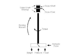
Figure 1. Various forces contribute to the load that a shaft must contend with.
First, the torsion and bending loads, previously calculated for shaft design, must be used to design the mounting. However, typical designs for tanks and structural supports do not adequately account for the dynamic nature of mixer loads. A support structure such as a beam in a building can withstand considerable flexure without failing. The bridge structures used to support mixers over large open tanks can have enough flexure to cause motion sickness in someone standing on a support that does not have adequate stiffness. The same flexure can result in considerable movement with a dynamic load such as a mixer.
Just as allowable stress levels for shaft design must be kept well below yield stresses to avoid fatigue failures, support design must include adequate margins to provide sufficient stiffness. Static load designs typically use 2.5 times the calculated torque and 3.0 times the bending loads to avoid large deflections in the mixer supports.
Second, the axial loads, which are not a real factor in shaft design, become much more significant in mounting design. The static weight of a large mixer can be considerable when including the total weight of a motor, gear drive, seal assembly, shaft and multiple impellers. These downward loads are important but so too can be the upward load caused by tank pressure. With large pressures, the flanges, pedestals and drive bearings all must be strengthened to handle increased loads. The mixer shaft passing through a seal acts like a piston in transmitting force, which can be significant. For instance, a 3-in-diameter shaft (cross-sectional area of 7.07 in2) in a vessel at 300-psi pressure will create an upward force of 2,121 lb on the mixer drive and supports.
The nozzle or pad mounting for a mixer (Figure 2) requires that support be distributed across the head of the tank. A nozzle uses gussets to provide sufficient stiffness and support. A reinforcing or stiffening plate, called a “skull cap,” often is formed to the head of the tank to increase stiffness around the nozzle or pad. Without this reinforcement, the head must be thicker and more expensive. The reinforcement also reduces the possibility that the outer ends of the nozzle gussets can cause fatigue cracks where stresses are concentrated. Within practical limits, the better the mixer is supported, the less likely other failures will occur.
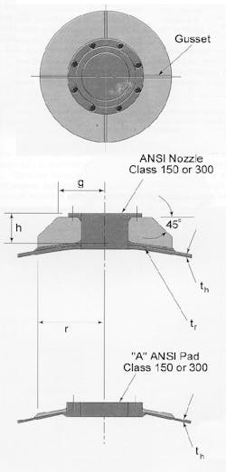
Figure 2. It is crucial to provide adequate stiffness and support.
A flexible or weak mounting will lead to other mechanical problems. Deflections in the mixer mounting may result in a bent shaft or worn shaft bearings. A flexible mounting also may allow vibrations that will prompt premature seal failures. A weak mounting will decrease the first natural frequency of the mixer shaft — and thus may cause critical speed problems not anticipated in the mixer design.
Make the most of your mixer
A mixer can best solve process problems if it isn’t hampered by mechanical problems. Moreover, always keep in mind that a mechanical problem also can be a safety problem.
An appreciation of design considerations and methods puts you in a better position to identify some of the more common mechanical problems and even suggest possible solutions. For new equipment, the more the manufacturer understands about your process, the less likely that mechanical problems will develop later. For existing equipment, avoid increased bending loads and operating near the critical speed to prevent major mechanical problems.
For more information about mixer design, see the chapter on “Mechanical Design of Mixing Equipment” co-authored by David Dickey in the Handbook of Industrial Mixing, John Wiley & Sons, Inc. (2004).
Dr. David S. Dickey is senior consultant at MixTech, Inc., Dayton, Ohio. He was the Winner of the 2005 Award for Excellence and Sustained Contributions to Mixing Research and Practice from the North American Mixing Forum, an affiliate of AIChE. E-mail him at [email protected].