Basic pneumatic conveying is a straightforward process. Proper evaluation of performance requirements and product characteristics are vital parts of that process. In addition, careful choice of the type of system and its components help create a pneumatic conveying system that efficiently and reliably contributes to the performance and dependability of the entire process unit.
The system designer and process engineer should carefully consider many factors when choosing a positive pressure, negative pressure or combined system. In addition, key components such as blow tanks, rotary valves and filters have to be well matched to the task at hand.
Positive pressure systems
Figure 1. Choose Wisely
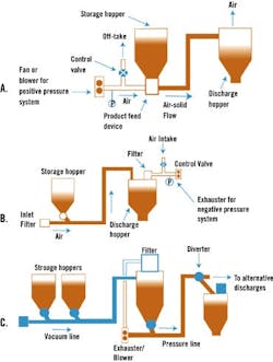
The choice of a positive pressure (A), vacuum (B) or combined (C) system will be defined by product feeding and/or discharge requirements.
Multipoint feeding of a positive pressure conveying system generally is not recommended. The air loss from a single feeder subject to leakage can be a significant proportion of that required for conveying the product. The loss from a number of feeders, if they are not isolated by additional valves, could be very high.
The air loss from a number of feeding points could be difficult to estimate accurately. So, the air available for conveying, which is a crucial requirement, could not be guaranteed. Apart from problems associated with having too little or too much air for conveying the product, the loss of a large quantity of air from a number of feeding points also would represent a very significant energy loss for the system.
Negative pressure systems
A vacuum conveying system is not the answer if multipoint discharging of product is needed, since such a system requires complex arrangement of pipework and isolating valves. These valves are sometimes found in low-pressure systems where ductwork is used. Valves in the ductwork, however, have to seal effectively, otherwise the air leakage into the system will adversely affect conveying.
If air leaks into a negative pressure system, it will alter the balance of conveying air velocities along the length of the pipeline. If air ingress is not accounted for in the air mover spec, the line is likely to block. If the air mover is over-rated to allow for air leakage, product flow rate will be reduced. Air ingress is likely to occur along a pipeline at flexible sections such as those used in off-loading systems, particularly if the conveyed product is erosive and the joint is hard metal or ceramic material.
Combined systems
Operating pressures also will differ. With a Roots-type blower, for example, a pressure ratio of 2:1 is generally considered the upper operating limit. Thus for a positive pressure system the maximum delivery pressure is about 1 bar gauge. For a negative pressure system the maximum exhaust pressure is about -0.5 bar gauge. For a combined system, the limit on pressures is approximately 0.4 bar gauge on blowing and -0.3 bar gauge on vacuum.
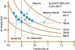
Since the two parts of the combined system operate at different absolute pressures, the pipelines likely will be different diameters. Figure 2 illustrates this point.
Figure 2. Combined System Requires Two Pipe Sizes
Conveying air velocity as a function of air pressure, with lines of constant pipeline bore plotted, shows a typical negative-positive system superimposed for a free air flow rate of 0.3 m3/sec. Balance between the two parts of the system, in terms of conveying air velocities, is achieved with different pipeline bores.
Air also probably will leak across the feeding device on the positive pressure side, so the air flow rates will differ. An imbalance in product flow rates between the two halves of the system necessitates a full assessment of the operating pressures, pipeline bores and air flow rates.
System component problems
Blowers:
If a blower is operating in a dusty environment, a filter should be fitted to the air inlet. This filter should be cleaned or changed periodically. If it becomes choked with dust, the added resistance will affect blower performance. An outside air source is generally the answer.
In negative pressure and combined systems, blowers have to operate with air that has been used for conveying product. In these cases, the air must be effectively filtered. It might also be necessary to add a backup to the filter, to provide a measure of protection for the blower should the filter unit fail.
A change in conveying system performance over a period of time may indicate blower wear. A small diet of dusty air into a blower will cause a gradual change in its operating characteristics.
Blow tanks:
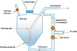
Figure 3. Blow Tanks Batch It
Single blow tank systems operate in a batch mode. Of all system components, blow tanks are probably least understood in terms of operation and control.
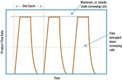
It is important to realize that to obtain a required time averaged mean value, the pipeline bore and air requirements must be based on the steady-state value achieved during the conveying cycle. If the desired product flow rate is not being achieved, consider means of increasing the ratio of the time-averaged mean to steady state values. Assess the times required for pressurizing, depressurizing and venting, valving and possible changes in operating procedures and conveying conditions.
Proportioning the air supply between the fluidizing and supplementary air lines controls the discharge rate of a blow tank. If insufficient product is being fed into a pipeline, the proportion of the total air supply that is directed to the blow tank should be increased. If too much product is being fed into a pipeline, this proportion should be reduced.
Figure 4. Blow, No Blow
For a given time-averaged mean value of product flow rate to be obtained from a blow tank, a very much higher value must be achieved during the steady-state portion of the cycle.
The discharge limit of the blow tank will be reached when all the air is directed to the tank. A further increase in product flow rate can be achieved by boosting the volumetric flow rate of the air, but this will have an adverse effect on the conveying of the product in the pipeline. The alternative is to increase the diameter of the blow-tank discharge pipe.
If a blow tank is to convey a product over a range of distances, the proportions of the air will change according to the distance conveyed. If this is not taken into account, the pipeline will be underutilized for shorter distances, and may block on longer distances. Here, a pressure gauge in the air supply line is particularly useful, for it can ensure the product flow rate through the pipeline is always the maximum that can be conveyed with the given air supply, regardless of conveying distance.
An automatic controller proportions the total air supply between the blow tank and the supplementary line. Control is usually based on pressure signals since, assuming that the blower or compressor operates within a prescribed range, any change in conveying rate, and hence phase density, will be reflected in a change of operating pressure.
If too much product is discharged into the conveying line, the pressure will increase and so the modulating valve will decrease the proportion of air passing to the blow tank to compensate. If the pressure drop across the conveying line is low, the modulating valve will reduce the supplementary air and so allow more air to pass to the blow tank and hence increase its discharge.
Air moisture is another concern. When air is compressed, its capacity for supporting water vapor decreases. Even relatively dry air will reach its saturation point and condensation will occur as the pressure is increased. Unless positive measures are taken to remove it, this moisture will be transported through the air supply lines with the conveying air. If a fluidizing membrane is used in a blow tank, this water will blind the membrane with certain products,"causing a gradual increase in pressure drop across the membrane and a resultant decrease in output of the system.
Most problems associated with moisture can be overcome by drying the air. If the product is hygroscopic, it will probably be necessary to incorporate a desiccant-type drier. If moisture and condensation are to be avoided, then a refrigerant drier should suffice.
Both the blinding of a fluidizing membrane and a restriction in the discharge pipe will add to the pressure drop across a blow tank. If the pressure drop across the product feeder increases, the pressure drop available for conveying the product in the pipeline will decrease and, so, cut conveying capacity.
Part of the blow tank pressure drop occurs in discharging the product from the blow tank. This is particularly a problem in top-discharge blow tanks requiring a long discharge line. The conveying air should be introduced as close to the tank as possible to minimize this pressure drop. In a tall blow tank it may be necessary to bring the discharge line out through the side to reduce its length.
The performance of a blow tank can be monitored quite easily by pressure gauges. A pressure gauge installed in the supplementary air supply line will effectively give a measure of the conveying-line pressure drop, and hence the use of the pipeline in conveying the product. A pressure gauge in the blow tank will then give an indication of the pressure drop across the blow-tank discharge line. If the blow tank has a fluidizing membrane, a pressure gauge in the air supply line to the blow tank will help monitor the state of the membrane.
With top-discharge blow tanks, there is also a minimum discharge limit, which relates to the fluidization air velocity in the discharge line.
If an attempt is made to convey a product at a low velocity from a top-discharge blow tank with only a small proportion of the air flow rate directed to the blow tank, the blow tank could "stall" and cease to discharge product into the conveying line. This is because the air velocity in the blow-tank discharge line will be very much lower than that at the product pick-up point. For a product having poor permeability and air retention properties, this could result in a blockage of the discharge pipe. If this occurs, use a smaller diameter discharge pipe.
Granular products can cause discharge problems from a top-discharge blow tank. Air permeates very easily through these products and it is possible that insufficient resistance will be built up to discharge the product. Bottom-discharge blow tanks are generally recommended for granular products.
Because of their high permeability, granular products require a higher proportion of air directed to the blow tank for a given rate of discharge than that needed for powders.
Granular products with a high percentage of fines are very much less permeable. They generally are not suitable for dense phase conveying in conventional systems. They will require very little air for their discharge from a blow tank, and so if the discharge line is unnecessarily long or has a long horizontal section, the discharge line is likely to block.
Rotary valves:
It is essential to feed a conveying line at the correct rate. If the feed rate is too low, the pipeline will be under-used; if too high, the pipeline could block. Varying the rotational speed of the rotor can provide flow control. There is an upper limit for any given size of valve, however, for the pocket filling efficiency will decrease with increase in speed.
If a variable-speed drive is used, the flow rate will be infinitely variable, as it is with a blow tank, up to its maximum capability with a product. If some form of gearing is provided, only step changes will be possible. Many rotary valves are dedicated to a single product and duty, with no speed control incorporated.
Conveying over a different distance requires a corresponding change in feed rate. If a different product is to be conveyed, it is quite likely that both the pipeline and rotary valve characteristics for the product will be different.
Granular products tend to shear in a normal drop-through rotary valve. The product might prompt considerable vibration, which could shorten the life of the rotary valve and the drive motor. Cohesive products can cause a problem with the proper discharge of product from the rotor pockets. In this case, a blow-through-type rotary valve would be recommended.
Air leakage across a rotary valve primarily depends upon the rotor-tip clearance and the pressure drop across the valve. Leakage also varies with the product being fed. A cohesive product, for example, will help to seal the various clearances and reduce leaks.
Air leaking across a rotary valve means less air is available to convey the product. In specifying the air requirements for the air mover, leakage must be considered. This leakage represents a total loss of energy from the system.
The air leaking across the valve may interfere with the feeding of product into the rotary valve. In this case, venting might solve the problem. A certain amount of product could be carried over with the vented air, so the vent line must be kept clear. Air leakage will also increase in tandem with valve size. A larger-than-necessary valve probably will generate unnecessarily high air leakage as a result.
Rotary valves are not generally recommended for handling abrasive products. Apart from abrasive wear of the sliding surfaces, erosive wear will be severe due to the very high velocities of air leaking through the valve. Wear will increase rotor-tip clearances and boost air leakage. This, in turn, causes air loss in the conveying line that could ultimately result in pipeline blockage.
Filters:
Be aware that the sample of product you supply to a filter manufacturer for selection and sizing could differ significantly from that to be handled by the plant filter. If it is a friable material and the conveying air velocity is high, the product at the end of the conveying line could be very different.
Cloth filters will gradually block with fine product that cannot be shaken free, and performance will be less effective. Filter bags, therefore, require periodic replacement.
Operators can monitor performance of the filters to a certain extent by noting the empty-line pressure-drop values. A pressure gauge in the air supply or extraction lines enables checking of the empty line pressure drop. This pressure drop represents the combined resistances of the pipeline and filtration unit. If the pipeline is purged of product, any changes in pressure drop can generally be attributed to the filter. An increase in this pressure drop would indicate that filter cleaning is not effective and should be checked.
Alternatively, an additional pressure gauge could be positioned in the receiving hopper. A positive pressure system exhausting to atmosphere will give a direct reading of the pressure drop across the filtration unit. It also will let operators record an on-load assessment of the pressure drop on a regular basis. In a negative pressure system, the difference in pressure between the gauge in the receiving hopper and the gauge in the air extraction line will have to be taken.
With reverse-air-jet filters, ensure that the air supply for the filter bag is correctly connected and of adequate capacity, and the cleaning cycle timer is set and operating correctly.
The surface area of filter cloth required is largely based on the volumetric air flow to be handled. The ratio of flow rate to area provides an approximate face velocity. However, if the filter is in a negative pressure system, the volumetric flow rate will be significantly higher, necessitating a much greater cloth area to maintain the same face velocity as an equivalent positive pressure system exhausting to atmospheric pressure.
A check on the empty line and filter-unit pressure drop is important during commissioning and before any product is conveyed to baseline the pressure drop across the filter against the design specification.
In batch conveying cycles, air flow rate per unit time is not uniform. At the end of a cycle, when the blow tank is just empty, a large volume of air is stored under pressure in the blow tank and pipeline. Venting this air, together with the compressor output for conveying, generates a significantly higher filter duty. Take this high air flow rate into account in the specification of the filter. Isolating the blow tank from the conveying line when it is empty, and venting it separately can reduce this surge.
Elizabeth Knight is a senior consultant and Dr. Don McGlinchey is a consulting engineer at Glasgow Caledonian University's (GCU) Center for Industrial Bulk Solids Handling, Cowcaddens Road, Glasgow G40BA, U.K. Tel: (440) 141-331-3715. The authors wish to recognize the contribution made to this article by their esteemed colleague, Dr. Pedrag Marjanovic, who, the authors note with sadness, has since passed.
Most problems with filters generally result from incorrect specification of either the air flow rate or the expected particle-size distribution. Filter cloths and screens will rapidly block if they have to cope with unexpectedly high flow rates of fine, degradated powder. The net result usually is an increase in pressure drop across the filter, meaning a reduction in the pressure drop available to convey the product.Rotary valves come in a wide range of sizes and types, and probably are the most commonly used devices for feeding pipelines in low-pressure systems. The mechanism of feeding, however, gives rise to a number of problems, and in positive pressure systems allowance must be made for air leakage.Of all system components, blow tanks probably are least understood when it comes to operation and control (Figure 3). Single blow tank systems operate on a batch-wise mode and conveying is not continuous. Figure 4 depicts the transient nature of the flow.The rotary lobes in blowers are machined to close tolerances. Any ingress of dust or product into the machine will have a serious effect on the performance of the blower. Downstream of the blower, or any other air mover, non-return valves should be included in the air supply lines to prevent the possibility of back-flushing of products.Many problems encountered relate to the various system components. The problems generally result from either incorrect specification, or a failure to take account of the conveyed product properties. Not all types of system components are discussed here. Most of the problems associated with screw feeders, for example, are common to rotary valves, so simple representative components are considered.The available power for a combined system has to be shared between the two sections. If a Roots-type blower/ exhauster is used, the pressure capability on both the vacuum and blowing sides will be lower than what can be achieved with an equivalent machine used for single duty.A common disturbance in "pull-through" systems is vacuum loss, particularly with batch and intermittently operating systems. The cause of the problem often is the failure of the discharge flap to seal at the base of the receiver vessel. Consider a secondary (policeman) filter prior to the exhauster (Roots-type) to safeguard lobes from worn or perforated primary filter elements, etc. The requirement for multipoint product feeding stations in many air conveying systems may define system selection. Figure 1 provides a schematic comparison of the three main options.
