Get Up to Speed on Drives
A motor drive controls the speed, torque, direction and resulting horsepower of a motor. Such drives fall into two categories: AC and DC. A DC drive typically controls a shunt-wound DC motor, which has separate armature and field circuits, while AC drives handle AC induction motors.
Consider a simple application,"a fixed speed fan using a motor starter. You could replace the 3-phase motor starter with Variable Frequency Drive (VFD) to enable you to operate the fan at any speed up to its maximum,"and so to vary airflow by controlling the motor speed instead of the air outlet damper.
A drive (see Fig.1) can control two main elements of a 3-phase induction motor: speed and torque. To understand how, first we should review the basics of AC induction motors. As Figure 2 shows, the two basic parts of the motor are the rotor and stator; their magnetic interaction makes the motor work. The motor contains pole pairs. These are iron pieces in the stator, wound in a specific pattern to provide a north to south magnetic field (Figure 3).
Figure 1. Simple Application of a Variable Frequency Drive
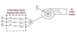
VFD allows fan to run at any speed up to its maximum and so provides an alternative to airflow control by an outlet damper.
With one pole pair isolated in a motor, the rotor (shaft) revolves at a specific speed: the base speed, which is a function of the number of poles, P, and the frequency applied, F. Figure 4 provides the formula for determining this speed, including the effect of "slip". Slip is the difference between the rotor speed and the rotating magnetic field in the stator. When a magnetic field passes through the conductors of the rotor, the rotor takes on magnetic fields of its own. These rotor magnetic fields will try to catch up to the rotating fields of the stator. However, they never do, and this difference is slip. Think of it as the distance between the greyhounds and the hare they are chasing around a track. As long as the dogs don't catch up to the hare, they will continue to go around the track. Slip is what allows a motor to turn.
Figure 2. AC Induction Motor Construction
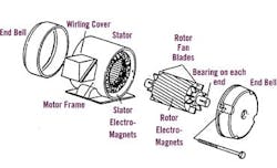
Magnetic interaction between the rotor and stator causes the rotor to revolve.
Figure 3. Stator Rotation
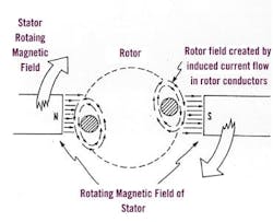
The specific pattern of winding iron pieces in the stator yields a north-to-south magnetic field.
You could adjust motor speed by changing the number of poles, but this involves a physical alteration to the motor. It would require rewinding and result in a step change to the speed. So, for convenience, cost-efficiency and precision, we change the frequency. Figure 5 shows the torque-developing characteristic of every motor: the Volts per Hertz ratio (V/Hz). We change this ratio to change motor torque. An induction motor connected to a 460-V, 60-Hz power source has a ratio of 7.67. As long as this ratio stays constant, the motor will develop rated torque. A drive provides many different frequency outputs. At any given frequency output of the drive, you get a new torque curve.
Figure 4. Motor Speed Formula
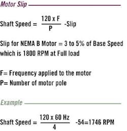
The difference between the rotor speed and that of the rotating magnetic field in the stator is the "slip" which causes the rotation.
Changing Motor Speed
Just how does a drive provide the frequency and voltage output necessary to change the speed of a motor? Let's look at Figure 6, which shows a basic Pulse Width Modulated (PWM) drive. All PWM drives contain these main parts, with subtle differences in hardware and software components. (Although some drives accept single-phase input power, we'll focus on the 3-phase drive. But to simplify illustrations, the waveforms in the following drive figures show only one phase of input and output.)Figure 5. Motor Voltage to Cycles Ratio
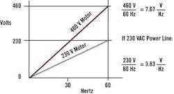
Changing the Volts to Hertz ratio changes a motor's torque.
Figure 6. Block Diagram of Pulse Wave Modulated Drive
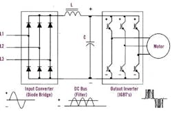
VSDs contain a converter to transform AC to DC, a filter section to smooth out the waveform, and an inverter to provide an AC output.
The input section of the drive is the converter. It contains six diodes, arranged in an electrical bridge. These diodes convert AC power to DC power. The diodes actually reconstruct the negative halves of the waveform onto the positive half. In a 460-V unit, you'd measure an average DC bus voltage of about 650V to 680V. You can calculate this as line voltage times 1.414.
The next section,"the DC bus section,"sees a fixed DC voltage and filters and smoothes out the waveform. The inductor, L, and the capacitor, C, together remove any AC component of the DC waveform. The smoother the DC waveform is, the cleaner the output waveform from the drive.
The DC bus feeds the final section of the drive, the inverter. It inverts the DC voltage back to AC, but provides a variable voltage and frequency output. How does it do this? That depends on the kind of power devices your drive uses. If you have many silicon-controlled-rectifier (SCR) based drives in your facility (Box, p.42). Bipolar transistor technology began superseding SCRs in drives in the mid-1970s, and, in turn, gave way in the early 1990s to Insulated Gate Bipolar Transistor (IGBT) technology.
Switching Bus With IGBTs
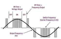
Today's inverters use IGBTs to switch the DC bus on and off at specific intervals. In doing so, the inverter actually creates a variable AC voltage and frequency output.As shown in Fig. 7, the output of the drive doesn't provide an exact replica of the AC-input sine waveform. Instead, it provides voltage pulses that are at a constant magnitude. The drive's control board signals the power device's control circuits to turn "on" the waveform positive half or negative half of the power device. This alternating of positive and negative switches recreates the 3-phase output.
Figure 7. Voltage and Current of Output Waveform
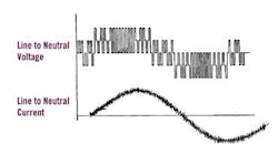
The PWM drive produces voltage pulses of a constant magnitude instead of an exact replica of the sinusoidal waveform of the AC input.
The longer the power device remains on, the higher the output voltage, and vice versa (as shown in Fig. 8). Conversely, the longer the power device is off, the lower the output frequency. If the "off" time was cut in half, the waveform would be half as long,"thereby giving twice the frequency output (twice the cycles in the same space). If the "on" time was cut by one-fourth, then the output voltage would only be one-fourth as much.
Figure 8. Frequency and Voltage Creation from PWM
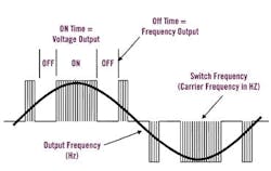
The longer the power device stays on, the higher the output voltage, and vice versa.
The speed at which power devices switch on and off is the carrier frequency, also known as the switch frequency. The higher the switch frequency, the more resolution each PWM pulse contains. Typical switch frequencies are 3,000 to 4,000 times per second (3K Hz to 4K Hz). (With an older, SCR-based drive, switch frequencies are 250 to 500 times per second.) The higher the switch frequency is, the smoother the output waveform and the better the resolution. However, higher switch frequencies decrease the efficiency of the drive because they lead to increased heat in the power devices.
Trimming Size and Cost
Drive designs continue to improve. Drives come in smaller packages with each generation. The trend is similar to that of the personal computer: more features, better performance and lower cost with successive generations. In contrast to computers, however, newer drives boast dramatically improved reliability and ease of use. Also unlike computers, today's typical drive doesn't spew gratuitous harmonics into your distribution system, nor does it affect your power factor. Drives increasingly are becoming "plug and play." As electronic power components improve in reliability and become even smaller, the cost and size of VFDs most certainly will continue to decrease while their performance and ease of use will only get better.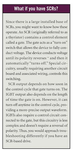
Dave Polka is Training Center Manager for ABB Inc., Automation Technologies, Drives, Motors and Power Electronics, New Berlin, Wis. He has been involved with AC and DC drive technology for more than 18 years.