Process Puzzler: Suppress Steam System Surprises

This Month's Puzzler
As part of our massive plant expansion, we added a new 200-psig boiler to our 30-year-old boiler. ASME inspectors de-rated our old boiler to 100 psig (see Figure).
We’ve had nothing but trouble. The relief valve blew on the new boiler shortly after startup. Even the old boiler is operating strangely with surges in the steam flow; its mud drum has a troubled history of corrosion.
We have a new steam-flow measurement for the old boiler that comes from a vortex-shedder-type meter. (Corporate wanted a Coriolis device but it was too expensive.) The meter gave a false high reading initially but then settled down; there is an unsettling variation in the reading. The flow measurement for the new boiler surged initially but also then stabilized. Rumor has it that one of our old operators did something. We convert the steam measurements from both boilers into mass measurements. The material balance for the new boiler doesn’t make sense with the feedwater.
Another issue is the oscillation in the pressure transmitter reading on the new boiler. This has caused some disturbances in the drum level measurement and material balance.
How can we get the boilers operating as reliably as the old boiler? Should we be concerned about a boiler control issue?
Check The Steam Rate
Two pieces of critical information are needed: 1) the old boiler’s original operating pressure; and 2) the old boiler’s steam rates (before and after the derate). I will hazard a guess that the old boiler used to operate at 200 psig and now operates at 100 psig but at the same steam rate, lb/h, as before. This would mean that it currently produces steam with a specific volume of 4 ft³/lb but was originally designed to make steam at 2.1 ft³/lb. The gas velocities have doubled, which can lead to poor demisting in the steam drum (demisters are overloaded) and a higher pressure drop through the superheater. This could potentially lead to a cycle of high dP, less boiling, low dP, more boiling, repeat. Try turning down the boiler to 50–75% to see if the surging stops.
Chris Rentsch, process development manager
Koch Modular Process Systems, Midland, Mich.
Look At Many Things
Consider the following:
1. Erratic flow readings by the vortex meter (on the 100-psig boiler). Look for vibration in the pipeline near the meter or two-phase flow (steam + condensate). Significant amount of condensate from the drain at the meter is an indication of excessive condensate. Make sure water level in the steam drum is low enough to minimize entrainment. Think about installing steam traps and ensure insulation is adequate.
2. Vortex meters are volumetric; they use pressure and temperature (density) estimation to get mass flow rate. Operation at pressure and temperature different from that in the design will show inaccurate flows and will affect steam mass balance. Mass balances done at mid-span of flow meters help improve mass balance accuracy. Some factors that affect mass balance accuracy are very low or very high flow relative to the flow-meter rangeability, meter accuracy and installation, and actual flow variations caused by varying steam demand by the plant operation. Generally, don’t expect mass balance to be exact — flow meters seldom add up exactly. (Vortex meters have Reynold Number limitations and typically work between 20 ft/s to 30 ft/s velocity, while the orifice meters have limited rangeability of 3 to 4.)
3. Before doing a mass balance, check, among other things, meter design flow rate, its span, (calibrate meters for their zero and span), installation (e.g., straight run before and after the meter, meter orientation), pressure and temperature compensation (if not provided in the meter design, you will need to use appropriate steam density from steam tables). Hold plant operations steady — or vary them in a pre-determined stepwise manner.
4. The three-element control on 200-psig is a common feature for high-pressure boilers with tight capacity of steam drums. You show elements as steam drum pressure, steam flow, steam drum level cascading the set point on the boiler feed water. The following points are worth noting:
• Oscillations in pressure indication on the 200-psig boiler. If the impulse line for the pressure transmitter does not drain the entrained condensate, it could cause oscillations. Ensure a free-draining impulse tubing.
• Instability of the three-element control could cause pressure fluctuations in the steam drum. Transmitters (flow, pressure, level), controller tuning, or the boiler-feedwater (BFW) control valve and its positioner could create instabilities. If you can put the control in manual and the pressure fluctuation goes away, improper tuning could be a cause of the problem.
• The sensors themselves could be another source. Check installation of the steam flow meter, level transmitter and pressure transmitter. Improper orientation or poorly installed sensing lines could lead to pressure fluctuations. Calibrate transmitters.
• Flow typically is a noisy signal. In addition, a tightly designed steam drum may have a lot of turbulence that could cause the level signal to be noisy as well. For a temporary solution, consider raising the damping setting on the flow, pressure and level transmitters. Of course, as we know, too high a damping setting could make the three-element control unresponsive to varying steam flows to the plant.
• The drum level preferably should be located in a relative quiet zone (say, a stilling well). In addition, steam drums make things worse for level measurement as they suffer from a shrink-swell problem that causes alternate bubble formation and collapse that will tend to make the level signal noisy.
• Relocating to a relatively quiet zone may require a shutdown. To avoid this, if you have spare nozzles on the steam drum, consider installing level bridles for level transmitters.
• For improving level reliability, some applications consider multiple level transmitters with voting arrangement, such as 2oo3. Unfortunately, this requires considerable amount of work and possibly a shutdown.
• An oversized BFW valve could lead to unstable control — which, in turn, could cause pressure oscillations. If the BFW valve stays barely open (say, less than 20% at the steam drum design rate), the valve likely is oversized. As a temporary solution, you might try to throttle a valve downstream of the BFW valve until the BFW valve opens up to controllable range (25–75% open).
• If the BFW valve hesitates and responds abruptly, the valve packing may be too tight.
• A smart positioner (BFW valve) with high gain could cause the three-element control to be unstable. Check gain on the positioner and lower it if necessary.
As there are many possible issues, try to prioritize. First do the low-hanging fruit that does not impact operations and avoids a shutdown, e.g., insulation, pipe support, calibration, tuning, and damping setting of transmitters (pressure, flow, level), before going to difficult items such as voting level transmitters or a stilling well in the steam drum that require a shutdown and significant redesign work. Coordinate closely with the operating and maintenance groups.
GC Shah, consultant
Houston
It's The Flow Loop
This is a control problem — for the small boiler and the new boiler.
The small boiler probably once had a large storage volume (drum) compared to steam usage, resulting in dead time; in lay terms, it was a slow-reacting system. F.G. Shinskey, in his book, “Process Control Systems,” p. 9, defines dead time. If the demand increased as part of the expansion, this single-element, proportional band (“bang-bang”) control system won’t respond fast enough to avoid surges. To some extent, decreasing the band width of the element can manage this surging. You’ll also want to make sure that nobody put integral or differential terms in the loop. If tightening the proportional band doesn’t work, then, regrettably, you may want to experiment with integral. All control loop designs should be trial-and-error, at least to some extent.
Because three-element is more complicated, the solution(s) are harder to find. You must consider six interactions, instead of one, between the principal process variable, the drum level and the flow of steam from the drum.
I think the biggest problem with the new boiler controls is the flow measurement. Bela Liptak’s Instrument Engineers’ Handbook, 4th edition, Volume 2, p. 1,576, Table 8.6d, has a nice summary of flow errors in boiler control for various types of flow meters.
From the figure, a magnetic flow meter measures soft water flow to the drum. A standard orifice is used to measure the steam flow from the drum.
Although the table does not include magnetic flow meters, from my experience their accuracy is comparable to the vortex shedding type at about 0.5–1% inaccuracy over the entire range of 10:1 turndown. This is excellent accuracy. However, taking errors in the transmitter and distributed control system into account, I reckon accuracy at 1–2%.
From this table, the inaccuracy of the steam orifice is horrible at 10% of design (maximum) flow; 2–5% at 33%, and 0.5% at 100%. Again, I think these numbers are low but they illustrate the “crankiness” of the new boiler controls at startup and shutdown. What you’re trying to control with a three-element system is the drum pressure. I see possible three solutions: 1) replace the steam orifice with a Coriolis meter (keeping the transmitter remote to protect against temperature) and replace the water meter with a Coriolis unit; 2) run the new boiler as a single-element system off level during startups and shutdowns, when the orifice accuracy is worst; and 3) tune-up the controls.
Note that I don’t propose vortex shedding meters for steam because of condensate buildup during pre-startup. Vortex meters infer flow from velocity; this buildup reduces the throat in the meter, increasing the velocity and, thus, causing a false measurement of high flow.
Coriolis meters are susceptible to inert gases and condensate but meters of this type are more sophisticated, so meter programing may work it out.
Tune-up suggests that workarounds could ameliorate the pressure spike causing the relief valve lifting. Perhaps you could load a dummy value for the steam flow or use a mass balance calculation to substitute for the measured steam flow, temporarily. Working with a simulator might lead to some answers.
Dirk Willard, consultant,
Wooster, Ohio
December's Puzzler
Our batch reactor (see Figure 1) has worked flawlessly until the last outage. Corporate quality control is screaming bloody murder about product contamination. We switched some of our ingredient suppliers a month before the outage and only ran a few batches before the outage.
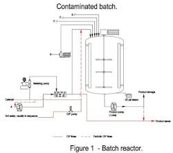
Recently, the steam expansion joint collapsed but I don’t see how that’s a factor in this investigation. Also, despite complaints by operations, we now have reduced the cost of the clean-in-place (CIP) step by flushing the reactor every third batch instead of every batch; it’s a bright idea from our corporate engineers. We continue to flush the static mixer because of the reactivity of the catalyst and the high viscosity of liquid blended with it.
Did the change in the CIP frequency affect our quality? Could it stem from a quality control problem with our ingredients? Could the change in impeller type or size of the bottom impeller be the cause? Should I be looking at the programming? Is it really contamination or is something else going on?
Send us your comments, suggestions or solutions for this question by November 11, 2022. We’ll include all of them on ChemicalProcessing.com. Send visuals — a sketch is fine. E-mail us at [email protected] or mail to Process Puzzler, Chemical Processing, 1501 E. Woodfield Rd., Suite 400N, Schaumburg, IL 60173. Fax: (630) 467-1120. Please include your name, title, location and company affiliation in the response.