Lessons Learned and Top Strategies for Fouled Distillation Towers
Fouling is a common problem in many distillation services, and there are general guidelines to address it. However, solutions may vary as each process has unique mechanisms. Two Dow plants faced ongoing fouling problems despite following these guidelines, prompting the need for customized solutions.
One plant had a small-diameter, random-packed tower and the other involved a larger-diameter tower packed with grid. The examples provide valuable lessons that were not initially obvious to me as a process engineer, offering a fundamental understanding of the causes of fouling issues and solutions to adequately address these problems.
Case 1: Defeating Salt-Fouling Woes in Tower Operation
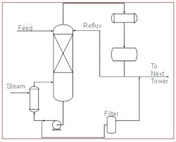
This first example involves a tower with a very deep bed (>25ft) of grid packing. The incoming feed stream contains a dissolved salt component. The salt will only precipitate if one of the chemicals from the feed mixture is stripped overhead. The primary objective of this tower is to remove salt from the solution and capture it using a filter on the bottoms stream to prevent fouling in downstream equipment.
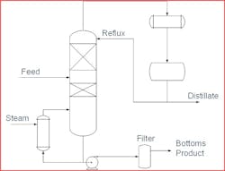
As shown in the process diagram (Figure 1), the bottoms and distillate streams are recombined before feeding to the next tower. Most of the salts pass through the tower as intended, but some accumulate over time, leading to the eventual fouling.
Historically, the tower can only run for approximately three months before the fouling becomes too severe to operate. When this occurs, there are several signs indicating the column needs maintenance, most notably the column floods and massively entrains liquid into the overhead accumulator. Leading up to this event there were signs fouling was occurring, such as a steady increase in the column differential pressure over time, a loss in separation capability for the volatile solvent, and a temperature inversion within the packed bed.
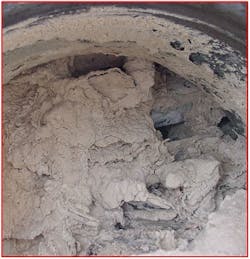
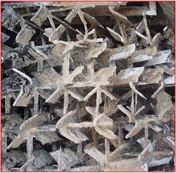
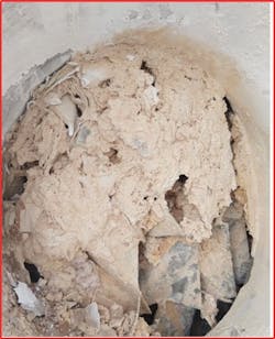
Figure 2 shows the extent of the fouling, which is severe. This photo was taken from the manway at the bottom of the packed section. Fortunately, the salts are easy to wash away with water, as shown in Figure 3.
New grid offers hope
This fouling problem persisted for years, with the plant making many attempts to increase the robustness of the tower through operational changes. One example was higher hydraulic loading to keep salts washing through the tower. This had little to no effect on the duration between fouling events.
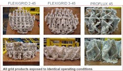
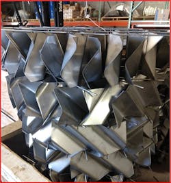
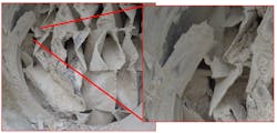
Advances in grid-packing technology offered new hope as a solution to this issue. Figure 4 shows testing data for various grid packings in salt deposition service provided by Koch-Glitch. Under the same test conditions, Proflux grid looked to be much more open and less plugged compared to the Flexigrid 45, which was the incumbent packing type. This presented strong evidence that a change to the internals could improve robustness. Beyond this external evidence, Dow has used Proflux to replace other styles of grid in other towers within the company’s operations, and in every case the tower has shown an improved resilience to fouling.
After seeing signs of more open internals, we decided to repack the tower and test it.
The tower immediately showed signs of enhanced separation capability, achieving a few extra separation stages beyond what was possible with the old grid. However, the fouling persisted, and the frequency of fouling events increased. The tower previously operated roughly three months between outage events, but now it was only lasting about five weeks.
Troubleshooting accelerated fouling
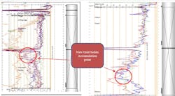
We gamma scanned the tower several times at different fouling stages to determine what was happening. We compared these newer results against the historic scans when the previous grid packing was in service. The results showed a distinctive difference in the way solids accumulate.
As shown in Figure 7a, with the historic scans, the solids previously filled the tower top to bottom before there was an operational issue. With the new grid, the solids seem to be much more concentrated in one location/elevation, while much of the tower looked relatively clean. Recalling that the salt precipitation is driven by removing a light component, we believed that the added stages in the tower led to a sharper split in the composition profile and location where the salts start to come out of solution.
Why did things get worse?
Armed with this new evidence the issue became apparent. Solids were accumulating on the new grid as expected, but what wasn’t expected was that the solids were sloughing off. These large chunks of solids would clog the flow channels and lead to the premature flooding of the tower. The chunks of solids are so large due to the large surface area of this grid compared to the previous style. Layers were roughly twice as tall with the new grid and were a continuous solids surface. In addition to being shorter, the old grid had several ridges to break up the surface. It’s likely the previous grid had something similar occurring with the salts, and the chunks sloughing off were smaller, so more were able to pass through the tower.The previous grid style may have been advantageous in this application as it allowed material to navigate around clogged channels and find an open flow path through the tower. As previously mentioned, multiple systems indicated maldistribution, and material maneuvering around clogged pathways was likely the cause.
Getting around the problem
Now that there was a better understanding of the solids and how the grid was working for this tower, efforts shifted to improving the current situation. Remember, salt precipitation occurs by eliminating the volatile component from the feed stream, believed to happen below a certain concentration. This was essentially verified correlating the location where the salt seems to accumulate the most against a composition profile generated from a process simulator. Then, someone proposed an idea to leverage this more efficient packing by diverting a portion of the feed around the packed bed while ensuring that the effluent from the sump contains a sufficiently low concentration of the volatile component to induce salt precipitation. The more material bypassed around the grid, the longer it would last before fouling would render it inoperable.
The team installed a bypass line that allowed feed to be introduced to the sump above the reboiler return. To enhance the overall mass transfer, we included a pipe insert to promote streams of liquid instead of pouring the feed through an open nozzle. The results have been extraordinary, and a substantial portion of the feed has been bypassed around the grid without any fouling impact downstream. This has extended the operating life significantly. With the location of the sump feed device above the reboiler return there is a significant amount of flashing and countercurrent flow with the incoming stream. This is providing far more mass transfer than was originally anticipated and has allowed a significant amount of the feed to be bypassed while still achieving the required composition. The results are still early but indications are we now have a solution to this problem.
Case 2: Immobilized Mobile Solids
The second example has a similar story. This process also has a foulant material that can’t be filtered out ahead of the tower. The foulant is dissolved in solution and only drops out after a volatile component is removed. The tower uses random packing in the beds above and below the feed. The intent of the design is for the solids to drop out in the tower and then pass through to a filter on the bottoms product stream (Figure 9).
Historically, the tower can only run for approximately six months before the fouling becomes too severe to operate. Once fouled, the symptoms were high-differential pressure and an inability to achieve the desired composition profile and heat input. When this happened, we had to take down the tower and replace the random packing with fresh packing.
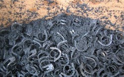
We discovered the fouled packing always had a lot of loose solids with it. In the first example, the solids coated the packing, but here the photos and experience of the turnaround personnel indicated the solids accumulate in the system but aren’t necessarily stuck in place. Figure 10 below shows pictures from packing changes, and in each case it’s clear the solids aren’t bound to the packing. The fouling is localized to only below the feed, with no fouling in the upper bed.
Discovering the problem
Wanting to eliminate the outages related to fouling, we launched initial troubleshooting efforts to better understand the situation. Through interviews with personnel that change the packing, we observed that the solids are always the worst at the bottom of the packed bed. There was no record of what was being used as a packing support, so we removed the packing support for the bottom bed for examination.
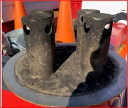
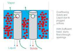
We realized the device being used to support the bottom-packed bed more closely resembled a distributor instead of a packing-support device (see Figure 11). There were very small orifice holes in the deck, which likely plugged off very quickly with the solids in the system. After this happened, solids and liquid backed up until they could leave via the larger holes in the risers. Overall, this device had very little open area and would cause a big restriction to flow. These findings led to the obvious conclusion that this was a big part of the problem and needed to be replaced.
The solution: Install a gas-injection-style packing support — something with a tremendous amount of open area to enable solids to pass through. Comparing this against what was originally in the tower, it seemed like this should significantly improve the issues being seen by the plant. This device was rushed in during the turnaround, and the process was returned to service.
We monitored the process after the change, and surprisingly, the fouling accelerated. Instead of lasting for six months between cleaning events, now the process lasted as little as two months. This was a major loss in capability.
Troubleshooting accelerated fouling
The solids in this tower consistently appear mobile but do appear to get hung up in certain places. The plant had developed a methodology for temporarily alleviating the fouling issue in the tower. This was accomplished by introducing a large, rapid burst of nitrogen at the bottom of the column (known as “nitrogen fluffs”). This consistently would result in a reduction of differential pressure, and a temporary return to more normal operations for a while. When the previous packing support was in place, these nitrogen fluffs would result in an extra four or five filter changes during a shift. By comparison, with the new packing support installed, a similar fluff would result in over 30 filter changes, illustrating how much more solids are being held up. This data also shows that accumulated solids can still pass through if disturbed.
To better understand the movement of the solids and the fouling, I reached out to solids expertise within Dow to gain their perspective. It was in these conversations that the experts believed the solids seemed to be mechanically arching across the openings. Mechanical arching is where solids can align in such a way that they bridge across openings, forming stable structures that then accelerate fouling as the pathways become more congested. When the nitrogen is applied to the bottom of the column, this creates some additional upward force, which breaks the solid bridges and results in a sudden outpouring of solids. Figure 13 below illustrates this phenomenon.
Preventing mechanical arching
Mechanical arching is possible when solids can align in such a way to form stable bridges that can span across openings. In the solids handling space, it’s been observed that different geometries are better at preventing this. Most notably, a slotted opening seems to be the most robust shape against this as it promotes what is called one-dimensional flow. With a slot, most of the shape’s perimeter is associated with the long sides vs. the short sides. As material is flowing through, it would preferentially flow through across the long side of the opening, creating the one-dimensional flow. The solids will have the greatest success of forming a bridge across the shortest openings, which in the case of the slot would be the width. In the one-dimensional flow regime, most of the flow entering the opening would be flowing adjacent to the structure, causing erosion of the bridge, eventually leading to it breaking. This has been extensively studied in solids handling and the hypothesis is being extended here into a distillation tower, but the evidence aligns well with the theory.Third time is the charm
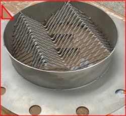
Equipped with this new understanding, we installed a third packing support in the column, which better aligned to the philosophy of a slotted design to help prevent the mechanical arches from forming. Results so far indicate a significant improvement in enabling solids to pass through. Findings are still early, but the plant has already exceeded the performance of the expanded metal packing support with the diamond shaped openings. It’s too early to tell if the situation is fully resolved but all data shows promising results and that the plan has made a significant step forward in fouling reduction.
Why did the original support do so well?
Regular packing support devices have some angle of inclination, but very rarely are they in a true vertical orientation. With the mechanism of mechanical arching, even with the circular opening, which isn’t as robust as a slot, it would be hard for the particles to align in such a way as to form a bridge in this vertical orientation.
The other contributing factor is the velocity through the openings was likely quite high. Since the overall support had very limited open area, vapor, liquid and solids had to fight to pass through the limited openings. The high velocities likely helped keep the opening clear for longer periods of time. When the device did eventually plug it was likely do to a large mound of solids that had finally built up from the bottom and couldn’t flow out the available openings. When this would get the nitrogen fluff, that would enable the solids to move again. This is shown in Figure 16.Through taking the extra time to better understand the fouling material and a lot of perseverance, industry can continue to make strides against long-standing fouling issues and hopefully move it further down the list of problems distillation towers face.
REFERENCES
1. Kister, H.Z., “Distillation Design”, McGraw-Hill, 1992
2. Kister, H.Z., “Distillation Operation”, McGraw-Hill, 1990
3. Jenike, A.W., “Storage and Flow of Solids”, Bulletin 123. University of Utah Engineering
Station, 1964 (revised 1976)
4. Schulze, D., “Powers and Bulk Solids”, Springer, 2008
About the Author
Greg Theunick
Senior Research Scientist
Greg Theunick is a senior research scientist at Dow, with more than 15 years of experience in the area of design, revamp and troubleshooting distillation processes. He holds a bachelor’s of science degree from Michigan Technological University in chemical engineering and is a licensed professional engineer in the state of Michigan.
