Dont let parallel pumps cross you up
Running two identical pumps in parallel can pose a number of problems, as one plant certainly discovered. It ran into both a common problem and a more unusual one.
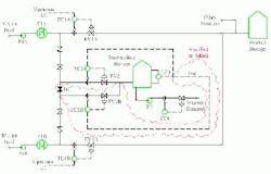
The plant had two parallel units that were identical in equipment but had some piping and layout differences (Figure 1).
Figure 1. Units A and B had identical equipment but some piping and layout differences.
The two units tied together in a common set of storage tanks. Additionally, an intermediate stream was drawn off and used internally as a cooled seal oil on some high temperature pumps. This system had been in place for many years. Insufficient seal oil had been a continual problem throughout this entire period.
The intent was to take the same amount of seal oil from each unit. However, the operators were forced to manually open and close the block valves to take seal oil from only one of the units at any given time.
Both the A and B units cycled as product rates changed over time. At various times during the operating cycle the intermediate storage tank would draw all the liquid from the product system and level control on the operating unit would be lost. The operators were continually switching between the A and B units in an attempt to maintain seal oil supply. Investigation showed two factors combined to make system control difficult.
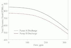
Nominally identical pumps can have different actual pump curves due to dissimilar maintenance histories, tolerances and wear. In some cases, the difference can reach 10% of head generated Figure 2 shows the impact on flow.
Figure 2. Identical pumps can actually differ by up to 10% in total dynamic head.
This is a common problem and was a factor here. While the difference wasnt 10%, it was enough to force the B pump product out of the intermediate draw nearly all the time when both units were connected. Additionally, small piping differences between the systems imposed a higher pressure drop on the B unit side, making the situation worse.
More importantly, the design suffers from a fundamental conceptual error. As product flow rates change at either unit, the one with less flow has a higher discharge pressure. With a higher discharge pressure available on one side of the combined header, more flow goes from that side of the plant to the intermediate product (seal oil).
The system as-built automatically pressure balanced to take more intermediate product from the unit that had the lower net product rate. Actual sensitivity depends upon system hydraulic balance. In this case, flow differences as small as 10% between each unit were enough to swing 100% of the seal oil draw from one unit to the other. Data showed product rates changed by more than 70% at times.
The solution was to add a second, independent control as well as to isolate the two systems upstream of the intermediate storage for seal oil (as indicated by the clouded area on Figure 1). After this change, the overall system was stable and operated very well. A bias controller between the two flow controllers (FC2 and FC2B) sets the ratio of seal oil coming from each unit. During occasional big shifts in product rates, the operators can reset this to rapidly get the system into control again.


