Correct those disturbing lapses
Some plants work despite design lapses. This presents two problems for the unit engineer or troubleshooter. First, getting away with a particular bit of sloppy engineering once leads to the temptation to do it again. If you push the edges of whats acceptable too often, eventually youll have a problem. Second, some marginal choices may occasionally work. So, when a unit develops a problem, it may be very difficult to tell whether or not the design deficiency really is the culprit.
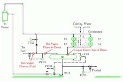
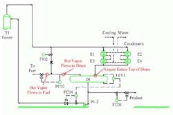
Lets look at one example of sloppy engineering. Figure 1 shows a familiar hot-vapor-bypass pressure control system (see "Take the pressure off pressure control").
Figure 1. The way liquid and bypass vapor enter the drum could cause problems.
Here, the liquid from the overhead condenser enters the reflux drum in the top vapor space of the vessel. Additionally, the vapor bypass from the column goes into the purge line from the drum instead of directly into the drum vapor space.
Hot vapor bypass works by keeping the reflux drum at non-equilibrium conditions. Proper operation requires that the condenser outlet be subcooled at all times. A warmer liquid layer insulates the bulk of the cold liquid from the hot vapor. Maintaining the warm liquid layer as still as possible reduces the amount of hot vapor condensed by the cold liquid. This minimizes condensation from the vapor space and allows for maximum unit capacity because it keeps the amount of liquid subcooling required as low as possible.
However, when the feed from the condenser enters through the top of the drum (as in this case), the falling liquid creates mixing between the subcooled liquid and the hot vapor. This is exactly the wrong thing to do. The fresh, cold liquid entering the drum shouldnt disturb the top liquid layer or directly contact the hot vapor.
Figure 2. Introducing condenser liquid from the bottom or via a pipe minimizes mixing in drum.
Figure 2 shows better designs that minimize mixing in the reflux drum and so improve system performance by introducing the liquid into the drum either from the bottom or, if top entry is a given, via an inside pipe that seals into the liquid layer. When putting a new hot-vapor-bypass system in place, the liquid from the condensers should always enter into the bottom of the liquid pool in the overhead drum.
Nevertheless, some drums with liquid entering through the top do work. So, when troubleshooting an existing system, dont automatically blame top entry for problems. The only way to know what will happen is to run the unit and see. When too much mixing takes place, the typical symptom is that the hot-vapor-bypass control valve goes full open and pressure still cannot be controlled.
The second questionable aspect in this example is the location of the hot vapor entering the drum. The bypassed vapor goes into the line from the drum to the pressure control purge (fuel in this case). So, the composition of the vapor to the fuel system is the same as that of the tower overhead. This wont cause poor performance but does change the composition of the purge gas. Running the hot vapor bypass directly to the drum (Figure 2) exposes the vapor to the drum liquid. Some selective condensation of heavy material takes place. The vent stream to fuel is a bit lighter than the tower overhead vapor. This may or may not be important. Most often, the hot vapor bypass should go through the drum.

