Properly Trigger Standby Pumps
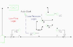
Critical services may require feed or product pumping at all times. In a typical parallel pump setup (Figure 1), one pump operates at all times. The other pump may be manually switched on or automatically started.
In such cases, control systems may include auto-start logic to bring standby pumps on as quickly as possible. This logic requires some signal to trigger startup — usually low pressure or low flow but level or another parameter may suit special situations. The turn-on trip point must be selected to avoid both misses and false positive signals.
Auto-start logic may become very complex. Some basic questions to answer include:
• Do you intend to run the same pump as the main pump at all times? In this case, you may want auto-start logic to apply only the secondary pump.
• Do you want to have the capability to run either pump as the main pump? In this case, you need logic that could start whichever pump is serving as the secondary pump.
For simplicity, Figure 1 shows the first case. However, the same considerations apply to both cases.
Pressure-activated standby systems typically cost less than flow-activated ones. A pressure sensor and associated control logic are cheaper to install and maintain than a flow measurement instrument. That’s why pressure-activated systems are most common; many use a low reading to switch on the standby pump.
However, sometimes pressure isn’t the right choice, as a comparison of two recent cases illustrates. Table 1 shows the pump and system characteristics for them. Both systems use centrifugal pumps.
| Pump | 101 | 103 |
| Pressure at suction drum, psig | 15 | 150 |
| Static head on inlet, ft. | 19.5 | 28.5 |
| Static head on outlet, ft. | 95 | 134 |
| Fluid specific gravity, normal | 0.68 | 0.52 |
| Fluid specific gravity, maximum | 0.69 | 0.56 |
| Pump type | Centrifugal | Centrifugal |
| Dynamic head at run out (maximum flow), ft. |
275 | 255 |
| Pump discharge pressure, normal operation at run out, psig |
102 | 214 |
| Pressure at pump discharge location, pump shut down, psig |
43 | 187 |
| Control range, psi | 59 | 27 |
| Control range, with 10% lower pump head, psi | 51 | 21 |
Pump 101 operates in a 15-psig system and generates 275 ft. of dynamic head. Pump 103 operates in a 150-psig system and generates 255 ft. of dynamic head. Both dynamic heads have been evaluated with the installed impeller at maximum possible flow rate for that impeller.
The lowest expected “in-operation” pressure at Pump 101’s discharge is 102 psig. If the pump shuts down, pressure at the discharge location drops to 43 psig. Over time this pressure will fall even more due to equalization of the static head on the pump suction and pump discharge. However, we’re most interested in short-term pressure to find a valid auto-start pressure setting.
The pressure-initiated auto-start setting must be lower than 102 psig and higher than 43 psig. The lower the pressure setting, the less risk of an auto-start due to a temporary low reading not from pump shutdown. The higher the pressure setting, the less risk of a pump shutdown that doesn’t initiate auto-start. For this system, finding an appropriate value between 43 psig and 102 psig isn’t difficult. The recommended value was 78 psig — this allowed some extra range to account for possible pump maintenance practices that might reduce the expected dynamic head at maximum flow.
In contrast, Pump 103 has a lowest “in-operation” pressure of 214 psig and a pressure at its discharge of 187 psig when the pump stops. This only gives a range of 27 psig, which drops to 21 psig if you provide a reasonable allowance for off-specification performance. It’s difficult to find a set point that will reliably auto-start the standby pump. So, a flow indicator for auto-start is a better choice.
Pressure-initiated auto-start doesn’t fit every situation. Pump type, performance, process conditions and operating characteristics may make using another parameter a better option. Make thoughtful choices to achieve your desired reliability.
Andrew Sloley is a Chemical Processing contributing editor. You can e-mail him at [email protected].