Slop Oil System Is Too Sloppy
THIS MONTH'S PUZZLER
We bought an old refinery with a history of safety and reliability problems. One area we're particularly concerned about is the current light slop oil system (Figure 1). The knock-out drum has a level transmitter that only covers part of the drum diameter, the containment area around the drum drains to the storm water sewer, and the slop-oil and sour-water level control valves are fail-closed. In addition, the minimum flow orifices of the knock-out-drum pump only are sized to prevent over-heating of the bowls. Then, there's the sump that the sour water empties into: it uses a simple bubbler for level control; there's no conservation vent or emergency vent, nor vapor space control in the sump pump room and the sump overflows to the ground. How should we establish our budget to modernize this system? Will we have trouble getting new permits? How can we improve the reliability of the equipment?
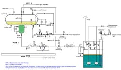
Figure 1. New owners want to modernize system to address several deficiencies. You can look at an enlarged view of this image.
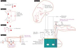
Figure 2. This layout includes significant modifications (shown in red) to the sampling valve (a), tank level setup (b), pressure safety valve (c), the sump (d) and valve (e). You can look at an enlarged view of this image.
I also suggest some mechanical changes for the separator. Add globe valves for the sample ports to reduce the risk of spilling and improve safety by having two valves for isolation. Spectacle blinds should be added to each inlet line for ease of maintenance of the drum. In addition, the separator secondary containment should have a locked sewer valve that goes to a process sewer instead of the storm water sewer; going to the storm sewer is illegal in many jurisdictions. I also would change the overflow for the sump from "to ground" to the process sewer or secondary containment. Depending upon the particular jurisdiction, adding a second level control instrument to the sump might be mandated. A review of the separator level control settings also will be in order.
The sump level measurement, a simple bubbler, requires improvement to a twin-tube. The second tube has a known distance from the bottom. This allows determination of the density using a local multivariable instrument, thereby compensating for the presence of oil in the sump; a simple bubbler is limited to a fixed density.
An open vent is not allowed in most jurisdictions. The NFPA, OSHA and EPA all have regulations regarding conservation vents and emergency vents for tanks that can contain a flammable liquid. OSHA's 1910.106 requires an emergency vent for liquids with a flash point below 100°F. Many jurisdictions mandate such a vent if the sump ever could contain such a liquid. Light slop might take you off the hook, but probably not if butanes could be present. Usually, the distillate from a second molar cut, found using a distillation model, is sufficient to determine if the composition requires an emergency vent if the worst-case composition can be estimated. Go here for more information on sump pressure relief.
Best engineering practice requires separation of hydrocarbons and other cancer-causing chemicals from vented gases — many jurisdictions also mandate this. That's where the activated carbon canisters come in. They are for trace concentrations; for more than 2 ppm mass, activated carbon is expensive if you can't regenerate it.
Another regulatory concern is the pressure safety valve (PSV) on the separator. So, make sure, for example, the inlet meets the 3% rule given in API 520; almost half of the inlets at one refinery didn't satisfy this stipulation. The PSV arrangement does not meet standards.
Now, let's consider reliability improvements. First, consider converting the level control valves from fail-closed to fail-open — unless downstream tank capacity is limited, which is unusual. Add a bypass for the valve to permit operation while the valve is replaced. Install flanges so pancakes or spectacle blinds can be easily installed to reduce risk to maintenance personnel. Add bleed valves before the pump check valves to more safely drain pressure from the pump when the check valve is closed; you may also want to look at thermal expansion in the piping, especially with block and bleed manifolds. Lastly, relocate the pump minimum flow lines and increase the orifice flows to reduce pump cavitation damage at low flow. The pump impellers may need to be upsized and the motor draw checked. Also, put in an additional valve or blind to the pump pressure gauges — but this isn't urgent.
Completely review the instrumentation and controls starting with the level alarms in the separator. The low-low alarms look too low. Add a high level alarm to the sour water boot and expand the slop oil level span to cover the whole diameter of the tank; this last item is crucial because the current level transmitter covers only up to the high-high alarm. The level gauges, if they are in working order, should be useful in determining liquid type. An alternative idea might be a multivariable level transmitter (LT) for density and level for the slop oil. Because a new nozzle will be required for the slop oil LT, the separator will require a new R stamp per ASME code.
And, lastly, insulate and heat-trace the vent piping to their destinations and include the PSV inlet. I recommend alarms on critical heat-traced sections if a blockage could cause equipment damage or mechanical integrity issues.
The vortex breakers inside the separator for each pump are a secondary concern. Usually, these are nice-to-haves; sometimes they are an obstruction if fouling is a problem.
Dirk Willard, project engineer
Superior Engineering, Hammond, Ind.
NOVEMBER'S PUZZLER
We're trying to resolve problems with our new two-stage countercurrent solvent extraction process. We use 2,000 lb/h of nitrobenzene (NB) to extract aniline from a 5,000-lb/h wastewater stream generated in the production of aniline. The process is supposed to transform the wastewater, which contains 5-wt.% aniline, into 4,750 lb/h of raffinate with 0.01-wt.% aniline, and give 2,250 lb/h of aniline-laden extract; our maximum contract discharge concentration is 0.25 wt.%. We're experiencing water carryover in the extract, which exits the process at the first stage. We can't achieve our contract limit, let alone our goal of 0.01 wt.%. We see about 1-wt.% aniline at the discharge. At operating temperature, the density of aniline is 1.018 g/cc, NB's is 1.12, and we use 0.98 for water. A stable rag layer has formed in both extractors; increasing the speed of the agitators has no effect. What can we do to achieve our goal and reduce the effects of the rag layers?
Send us your comments, suggestions or solutions for this question by October 13, 2013. We'll include as many of them as possible in the November 2013 issue and all on ChemicalProcessing.com. Send visuals — a sketch is fine. E-mail us at [email protected] or mail to Process Puzzler, Chemical Processing, 555 W. Pierce Road, Suite 301, Itasca, IL 60143. Fax: (630) 467-1120. Please include your name, title, location and company affiliation in the response.
And, of course, if you have a process problem you'd like to pose to our readers, send it along and we'll be pleased to consider it for publication.