Accurately Measure Interfaces Between Immiscible Liquids
Various liquid products, for reasons of molecule polarity or differences in specific gravity, resist mixing and, if left alone, separate into distinct layers. Many plants deal with such liquids and must track the amounts of specific phases in tanks and vessels and, perhaps, even flowing through a pipe. So, here, we will look at level instrumentation suitable for this task. We will use oil and water as an example but the principles of oil/water interface measurement apply to a wide range of multi-phase processes.
Often, a plant desires distinct phases either to ease recovery of product or removal of impurities and, so, includes a separator or other equipment to spur the splitting of components. Sometimes, just determining which material is at a given level suffices. In other cases, knowing the location of the interface between the phases is important.
Simple Situation
Let’s first consider when a plant only needs to ascertain what’s at a given level. In such a case, it’s usually important to have a sensor that’s immersible and can measure in real time without the need to withdraw a sample.
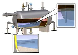
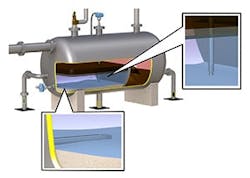
Figure 1. These can indicate if oil and water are at appropriate levels and if accumulated sand is taking up useful space.
Various detection technologies could do the job but one of the most economical and practical is a vibrating-fork level switch. It typically determines if the contents of a tank or vessel have reached or passed the instrument’s sensor insertion point. A fork extends into the space; a piezo-electric crystal causes the fork to vibrate at a specific frequency when in free air. When immersed in another medium, the frequency changes, which the instrument’s electronics detect. In many situations, just indicating when the fork is immersed is enough. However, some more-sophisticated devices can characterize what the fork is immersed in by the degree of change in frequency. This is because the sensor behaves differently when immersed, e.g., in water versus oil; so, it can indicate if it’s above or below the water/oil interface point.
You can use this capability in a variety of ways. Inserting multiple vibrating-fork level switches into a separator (Figure 1) in strategic positions can check that the oil and water levels are both where they belong. They also can determine where the water/oil interface point is and where it might be moving during filling or emptying sequences. In addition, a switch inserted into a pipe can indicate which liquid is flowing through at a given time; this, for instance, can help alert when all the water has been pumped out of a storage tank.
Yet, as versatile as it is, a vibrating-fork level switch only can signal whether it’s immersed and in what (if the possible liquid characteristics differ sufficiently). Such a point level device can’t indicate if it is deeply immersed or just below the surface.
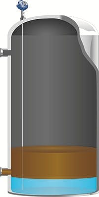
Figure 2. When emptying a tank filled with multiple liquids, knowing the interface level is necessary to avoid cross contamination.
Multiple Levels
Some applications require a continuous reading of the liquid level in a tank containing multiple products that separate into layers (Figure 2). Level switches can do part of the job, as just discussed, but the distance between the switches restricts measurement resolution. So, a plant should consider other options. The three main choices capable of measuring overall level as well as the interface below the surface are: magnetostrictive, guided-wave radar (GWR) and differential pressure (DP).
Magnetostrictive and GWR are somewhat similar in approach in that they both send an electronic pulse down a probe and calculate level based on the time of flight to the liquid surfaces and back. With a magnetostrictive instrument, the pulse is reflected by a float that is free to move up and down the probe, buoyed by the liquid to follow any change in its level. Floats come in different buoyancies and are chosen based on the specific density of the liquid. So, to locate a water/oil interface, the lower float is carefully tuned to float in water, whereas the upper float has greater buoyancy to float on top of the oil.
GWR also sends a pulse down a probe but doesn’t use a float. The pulse is reflected directly off the surface of the liquids (Figure 3) — the main reflection from the top and a secondary reflection from the interface layer. This works provided the liquid on top has a lower dielectric constant (DK) or relative permittivity than the liquid underneath. GWR suits sensing oil on water well because most oil products have a very low DK, <5 typically, while water’s is >50.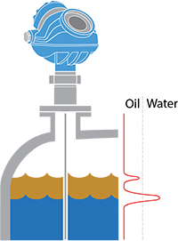
Figure 3. Pulse creates echoes both from the surface and the interface point.
DP measurements operate differently. They use the pressure produced by the height of the two liquids to determine the level and interface of the liquids. Making this work for an interface requires precise knowledge of the density of both liquids and, potentially, an additional overall level measurement. DP level measurements can run into difficulties with emulsion layers or varying densities.Magnetostrictive level instruments very accurately can measure the location of the float. However, that location isn’t always where it might be expected. The float comes to rest where it’s designed to float, so a change in the density of the liquid will change its final position. Additionally, situations can arise where residues coat the probe and floats, so they get partially or completely stuck in place, not moving freely or even at all in the worst cases. Obviously, this significantly undermines the accuracy of the measurement. Unfortunately, an operator may not be able to tell what’s happening beyond realizing the readings are not changing. A more insidious problem is a loss of accuracy if the float can move partially but drags, reducing its ability to find the true level point. This condition isn’t easy to recognize from the readings.
A GWR probe can tolerate some amount of buildup; so, in general, cleaning is unnecessary. Moreover, the instrument can indicate a developing problem of excessive buildup because the nature of the echo created by a dirty probe (Figure 4) differs from that of a clean probe. Some instruments with advanced diagnostics can quantify signal quality and send it as a secondary variable. Should signal quality ever drop below a critical level, an alert can warn operators of the problem so they can take appropriate action.
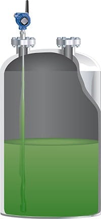
Figure 4. Buildup on a GWR probe eventually changes the profile of the echo in recognizable ways so operators become aware of the problem.
Indistinct Layers
One area where both GWR and magnetostrictive technologies struggle is emulsification of a tank’s contents. In some situations, the two products will separate partially but not sufficiently to create a distinct interface. An emulsion layer, where the two products remain mixed, forms in the middle; both magnetostrictive and GWR technologies will give misleading readings — but in different ways (Figure 5).
With a magnetostrictive instrument, whether or not a distinct interface exists, the lower float will come to rest where the density matches the float’s buoyancy. With an emulsion layer, the float will stay somewhere in the midst of the emulsion. So, if operators are unaware of the emulsion layer, they might assume all liquid above the float is oil and below is water. Using the float location to pull oil from the top likely will lead to getting some water, too. A DP measurement similarly depends on the densities of the liquids and also will give a measurement in the midst of an emulsion layer. However, you can recalibrate DP level readings for density changes. You can’t adjust the magnetostrictive float design.
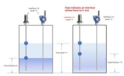
Figure 5. Magnetostrictive and GWR instruments respond differently to indistinct layers.
GWR has the opposite problem. It requires a fairly distinct interface point. This has to do with the way GWR detects a surface. When the pulse is moving down the probe, it sends an echo not due to hitting a liquid surface but because the surface represents a point with an immediate and drastic change in DK between air and the oil. The water/oil interface also must exhibit an immediate and drastic change in DK, as occurs between oil and water assuming a defined transition. Recently developed GWR transmitters can differentiate emulsion layers of about 50 mm. However, thicker emulsified bands aren’t always distinct enough and generate no second echo or one too undefined to be useful. As a result, the GWR instrument reports no interface.
In applications with emulsions, it helps to install a GWR instrument in a calm area of the vessel where the layers have the best chance to separate and, so, enable a better interface measurement. The use of a large coaxial probe or a stilling well can foster better product separation and, therefore, more accurate level measurements. However, a poorly designed stilling well can interfere with the separation and create an inaccurate picture of the interface point. If the holes or slots are too far apart, the interface inside might not match the rest of the contents. Slots must overlap to allow full circulation of the liquids.
Which of these measurement problems is more tolerable depends on the situation. Having some idea that there is an interface, whether distinct or not, might suffice in some cases. On the other hand, having the interface measurement fade to nothing might warn operators about a process upset or that an upstream separator is being run too hard.
Thin Layers
So far we’ve covered situations in which the two layers are both fairly thick. However, sometimes the secondary component only forms a thin layer. This poses difficulties for both magnetostrictive and GWR technologies.
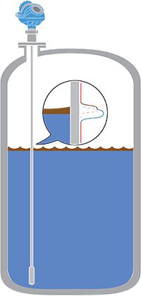
Figure 6. Measuring thin layers depends on an instrument’s ability to separate close echoes.
For magnetostrictive instruments, the floats create limitations due to their physical size. If the layer is thinner than the floats are long, they will touch each other on the probe. Even GWR instruments have minimum thickness requirements due to limitations on the ability to separate return echoes (Figure 6). Typical minimums for GWR vary between 125 to 200 mm depending on the specific make and model. Magnetostrictive instrument minimums generally are greater and depend on the particular instrument type and float size.
Newer, highly sophisticated GWR instrument technologies have improved the ability to resolve very short pulse-duration differences, allowing some of the latest models to measure well-defined thin interfaces down to 25 mm. This significant improvement results from improved software able to detect signal peaks that are closer together without having to decrease signal bandwidth.
The tools available to chemical makers working with immiscible products are improving. The ability to identify which product is flowing through a pipe or to accurately determine the contents of a tank with thick or thin layers can improve process control and possibly identify when something has gone wrong, allowing for timely corrective action. Such measurements can enable a plant to optimize processes and maximize operational efficiency and profitability.
LYDIA MILLER is senior product engineer, level, for Rosemount Measurement, Emerson Automation Solutions, Shakopee, Minn. Email her at [email protected].