Make The Most of Filter Aids
Many chemical processes require removal of fine solid contaminants smaller than 5 µm from liquids. When the suspended solids content is dilute, typically less than 1% by weight, the operation to produce a clean liquid product is called clarification or polishing filtration. Typical applications include catalyst recovery, polymer and resins, active pharmaceutical ingredients, removal of unreacted chemicals and byproducts, and polishing of gray water.
Often in polishing applications, the solids are very fine or amorphous, making them difficult to filter. When filtered, the solids will create a thin impermeable coating over the filter medium and immediately reduce the filtration rate to an unacceptable level.
In these difficult cases, filter aid pretreatment may improve filtration properties and efficiently remove the fine solids.
Filter aids can serve in the filtration cycles of various types of filters:
• Plate-and-frame filter presses;
• Horizontal and vertical pressure leaf filters;
• Candle or tubular filters;
• Nutsche filters; and
• Rotary vacuum drum filters.
Types Of Filter Aids
Diatomite, perlite and cellulose are the filter aids most frequently used in industry. Other organic materials such as potato starch particles and rice hull ash find some use but are less common. A filter aid requires certain key properties; it must:
• Consist of rigid, complex shaped, discrete particles;
• Form a permeable, stable, incompressible filter cake;
• Remove fine solids at high flow rates; and
• Remain chemically inert and insoluble in the process liquid.

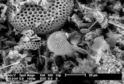
Figure 1. This material, Celite, is made of the microscopic silica skeletons of prehistoric plants. Source: Imerys Filtration Minerals Inc.
Diatomite. Also known as diatomaceous earth (DE), diatomite (Figure 1) consists of the microscopic silica skeletons of prehistoric plants. These skeletons are called diatoms. This material is mined and calcined to destroy any organic matter. The DE then is milled and separated into various filter aid grades via air flotation. The final product is a soft, powdery material resembling chalk.
Diatomite filter aids boast the advantage of a rigid and highly porous structure. When deposited on a filter medium, the DE forms a non-compressible cake and acts as a sieve to remove fine solids. The micropores in the diatoms allow flow through the particle while the fine solids are captured between the diatom granules. Being comprised mostly of silica, DE is inert in a wide range of applications.

Figure 2. Glass-like volcanic rock containing small particles with cracks is used to make this material, Harborlite. Source: Imerys Filtration Minerals Inc.
Perlite. This material (Figure 2) is formed from glass-like volcanic rock that consists of small particles with cracks that retain water and gas. The perlite is mined and then the ore is heated to its melting temperature. At that point, the molten volcanic glass expands and fractures due to the emission of the steam and gas. This expanded material then is crushed and classified to provide different filter aid grades.
Perlite has a lower specific weight than DE, which allows less filter aid to be used. The primary advantage of perlite compared to DE is its relative purity. Diatomite may contaminate process liquids with dissolved salts and colloidal clays that are inherent to it; perlite doesn’t share this risk.
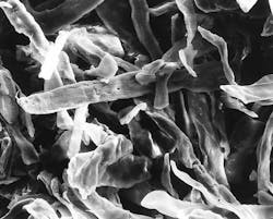
Figure 3. When filtration captures valuable metals, a combustible material like Fibracel can ease their recovery. Source: Imerys Filtration Minerals Inc.
Cellulose. This material (Figure 3) is used to a lesser degree than DE and perlite because of its higher cost and lower filtration efficiency. However, it does offer some advantages versus diatomite or perlite. Cellulose is combustible, which is useful in the recovery of valuble metals. Cellulose also is compatible with hot caustic solutions unlike DE and perlite.
Each type of filter aid comes in different grades that vary in particle size, which typically ranges from 5µm to 100µm. As particle size decreases, the ability to capture fine solids increases, thus the filtrate clarity improves. However, smaller size raises cake resistance. Therefore, the finer the filter aid is, the lower the throughput per unit area. These relationships mandate finding an appropriate balance between filtrate clarity and filtration rate. It’s important to use the largest possible filter aid grade that achieves the filtrate clarity target.
Because the solids differ in every application, there’s no rule for matching filter aid grade to suspended particle size. Instead, you should run benchtop-scale filtration tests with various filter aid grades. Measuring the rate of filtration and observing filtrate clarity will help you select the optimal product.
A filter aid requires a filter medium; this is the septum on which the filter aid solids are retained while the clear liquid passes through. Most often this medium is constructed of a woven synthetic polymer or alloys. It is supported by a rigid structure that also is porous to allow liquid to travel through.
The filter medium’s pore size should approximately equal the median particle size of the filter aid. The exact pore size isn’t critical so long as some filter aid is retained. Once the filter aid begins to build on the woven filter medium, the cake becomes the new primary surface for particle capture. Selecting a filter medium with too large a pore size will result in a long turbid cycle because the bridging of the filter aid will take a long time and may be unstable. Selecting a medium with too small a pore size will result in a reduced filtration flux rate due to the added resistance.
You can use different types of lab equipment for selecting filter aid type, process and filter medium. One option is the BHS Pocket Leaf Filter (PLF). This apparatus can perform benchtop-scale pressure and vacuum filtration tests, to determine flux rates, filtrate clarity, filter medium, cake thickness, washing and drying efficiencies, cycle times, performance versus quality parameters and qualitative cake discharge. The PLF is jacketed for heating or cooling and is rated 90 psig to full vacuum. It has a 20 cm2 of active filter area and a filling capacity of 400 mL. Figure 4 illustrates the set-up.
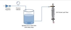
Figure 4. Bench-sale apparatus can provide insights for optimizing a number of parameters.
Utilization Techniques
Filter aids are used via two methods: precoat or body feed. You can employ the two individually or combined (as shown in Figure 5) to gain the benefits of both.
Precoat. Here, the filter aid generates a thin layer of solids on top of the filter medium. Once formed, this cake functions as the primary means of filtration. Therefore, the filter cloth no longer serves as the real filter when using precoat. For that reason, you should select a filter cloth that’s as open as possible while still retaining the filter aid material.
The precoat process involves mixing the filter aid into clear liquid or mother filtrate in a tank. Diatomite filter aids usually work best with a precoat slurry concentration in the 0.3–0.6 wt.% range. This slurry then goes to the filter where the filter medium captures the solids. The clean filtrate returns to the precoat tank. The precoat should be thick enough to ensure the medium’s entire surface is coated but thin enough to avoid significant resistance to filtration. To prevent the precoat from settling in the pressure vessel and creating an uneven precoat, a feed flow rate of 1 gal/min/ft2 is ideal. Typical precoat thicknesses are in the 1–3-mm range.
Using precoat in a clarification process offers several advantages. It helps prevent the filter medium from becoming clogged by the slurry fines, thus extending filter medium life. This is especially critical when filtering amorphous or slimy solids. Precoating also helps provide immediate filtrate clarity. The precoat layer acts as a depth filtration bed for trapping fine particles that typically would pass through the filter medium. In addition, precoat helps filter cake solids discharge at the end of a filtration cycle by providing a cleavage plane from the filter medium.
Body feed. This technique involves blending the filter aid with the slurry feed either by dosing concentrated filter aid suspension into the slurry feed and in-line mixing or by mixing the filter aid into the entire slurry batch and maintaining agitation.
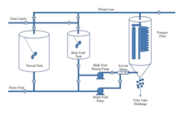
Figure 5. Flow diagram shows precoat and body feed processes with filter aid and filtration via pressure filtration.
The filter aid solids and the native solids continuously build a filter cake until either the maximum cake height or maximum operating pressure is reached. By adding filter aid into the slurry feed, the resulting filter cake is more porous, allowing higher and longer sustained flow rates. Body feed also helps restrict solids movement, which improves filtrate clarity.
The goal of the optimal body feed concentration is to maximize the flow rate of a filtration cycle while avoiding feeding too much filter aid solids. Using too much body feed will cause the filter to reach the maximum filter cake height faster than necessary. Employing a body feed without precoat can lead to an initial turbid filtrate while the cake begins to build on the filter medium. This initial turbid bypass generally will be much shorter than that observed filtering the raw slurry. You can recycle this turbid filtrate back to the slurry feed tank to ensure no solids bypass occurs.
Practical Pointers
Whether the process is precoating or body feeding, the filter aid slurry tank and pump are critical to the operation. The precoat mix tank should be a round vertical tank whose height is twice its diameter. Avoid rectangular or horizontal tanks. Set the usable volume of the precoat tank at ≈1.25–1.5 times the volume of the filter plus the connecting lines. Use a mixer or agitator with large slow-speed impellers to avoid filter aid degradation and the creation of fines — otherwise you’ll dramatically change the filter aid process filtration.
The precoating pumps almost always are centrifugal pumps because they produce no pulsations to disturb precoat formation. Such pumps typically are low speed (1,800 rpm) and low pressure as the precoating rate is much faster than the filtration rate with low pressure drop. Also, because the precoat pump is exposed to filter aid particles, its internal parts usually have hardened surfaces and open impellers to reduce wear. (For more on slurry pumps, see: “How to Succeed at Slurry Pumping.”)
For body feeding, use positive displacement pumps.
Even when the feed tank and pump are correct, operators can face several typical issues with filtration/filter-aid systems.
Bleed-through is common where the filter aid is bypassing the filter media. It may stem from mechanical, operational or process causes. Check a couple of mechanical points: Is the filter medium secured to the filter correctly? This will depend upon the type of filter. Does the filter medium have a tear or pinholes? From the process view: Is the type of filter aid correct for the filter medium mesh size and the particle size distribution of the process solids? If the filter aid particles are too fine compared to the filter medium opening, then it will take a long time for the filter to build a layer of solids. If the filter aid is too large compared to the solids being filtered, then the slurry solids may flow through the filter aid’s interstitial spaces. Finally, operationally: Is the pump working correctly (flow, pressure, etc.)? Is the proper amount of filter aid being added?
Reduced filtration cycles — i.e., the time to reach the maximum pressure drop becomes shorter and shorter — are common. This symptom may occur for several reasons. Firstly, if the cake isn’t being discharged completely, then each new batch has residual solids in the filter, resulting in lower capacities. Increasing precoat height or lengthening cake drying time may help improve cake discharge. Secondly, if the precoat doesn’t completely cover the filter medium, then the process solids may begin to blind the medium. Finally, if you’re using body feed, inadequate mixing with the process solids may result in filter medium blinding. This also can happen if the velocity in the filter vessel is too low, which will allow the filter aid to settle out before reaching the filter elements. A bypass at the top of the filter vessel can help keep the solids suspended within the vessel.
On filters with vertical elements, losing the precoat from the filter medium also can occur. The precoat pump flowrate or pressure may cause this. It also may arise if improper valve sequencing creates a sudden change in the pressure or flowrate. Finally, a mechanical issue with the filter may prompt a pulsation or pressure change that impacts the cake structure.
Apply Filter Aids Wisely
Employing filter aids to help filtration is a tricky business; most process operations try to eliminate or minimize their use. However, sometimes they are unavoidable, especially if a process requires very fine filtration where the filtrate is the product and the process solids are difficult in terms of shape, size and characteristics (e.g., slimy or amorphous).
To succeed with filter aids, a process engineer should take three essential steps:
- Conduct lab testing to examine the filtration operation (vacuum or pressure), cake thickness, filter aid quantities, filter medium and other parameters that are crucial to the process design;
- Ensure correct mechanical design to provide optimum precoat or body feed handling and distribution; and
- Arrange for operator training on the filtration technology as well as on filter aid operation.
By carefully taking these three steps, you will achieve favorable results on the project and process.
BARRY A. PERLMUTTER is president and managing director of BHS-Sonthofen Inc., Charlotte, N.C. GARRETT BERGQUIST is a sales engineer for BHS-Sonthofen Inc. Email them at [email protected] and [email protected].
FURTHER READING
Perlmutter, B. A., “Solid-Liquid Filtration: Practical Guides in Chemical Engineering,” Elsevier/Butterworth-Heinemann, Amsterdam (2015).
Sentmanat, J. M., “Engineering Principles of Precoating,” p. 40–46, Filtration News (April 2013).