Understand Industrial Wastewater Treatment
Process plants generally try to minimize the amount of wastewater they generate. However, operations invariably result in production of some wastewater. Proper treatment of this wastewater is crucial for both environmental and economic reasons.
Industrial wastewaters usually contain organic and inorganic matter in varying degrees of concentration. They may include toxic and other harmful materials as well as components that are non-biodegradable or that can reduce the efficiency of many wastewater-treatment operations.
Thus, treatment of industrial wastewaters typically is a very difficult task — far more complicated than municipal wastewater treatment —that requires special methods and sophisticated technologies. These options fall into three categories: physical, chemical and biological. Physical treatment methods include sedimentation, flotation, filtering, stripping, ion exchange, adsorption and other processes that remove dissolved and non-dissolved substances without necessarily changing their chemical structures. Chemical methods include chemical precipitation, chemical oxidation or reduction, formation of an insoluble gas followed by stripping, and other chemical reactions that involve exchanging or sharing electrons between atoms. Biological methods rely upon living organisms using organic or, in some instances, inorganic substances for food.

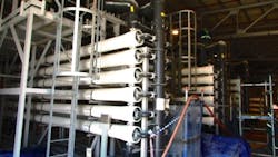
Figure 1. Use of such a unit for tertiary treatment of wastewater is becoming popular.
Biological treatment is more widely used than any other option where reasonably complete treatment is required. It most often serves as the secondary treatment stage to remove major portions of contamination. Other processes handle primary and tertiary treatment to complete the removal of solids and other pollutants.
The Challenge
Some industrial wastewaters are rich in organics and easily biodegradable while others are nutrient deficient, inhibiting or preventing biodegradability. Total dissolved solids and contamination may exceed by many times the levels found in domestic sewage. Industrial wastewaters often also have pHs well beyond the range of 6–9 and may contain high concentrations of dissolved metal salts. To further complicate matters, wastewater flows and characteristics within a plant also can vary with time because of campaign manufacturing or slug discharges on top of the usual discharges. In addition, spillages and dumping that occasionally may occur very adversely can impact the performance of the plant’s wastewater treatment plant. Consequently, it’s always prudent to carefully assess current wastewater and its treatment requirements rather than relying on the past situation. An understanding of the nature of the plant’s operations is vital.
One key parameter for wastewater is its biochemical (or biological) oxygen demand (BOD). This is the amount of dissolved oxygen needed by aerobic biological organisms to break down organic material present in a given wastewater sample at a certain temperature over a specific time period. Therefore, BOD indicates indirectly the amount of organic compounds in wastewater. The BOD most commonly is expressed in milligrams of oxygen consumed per liter of sample during 5 days of incubation at 20°C.
Another key parameter is chemical oxygen demand (COD), which indirectly specifies the amount of organic compounds in the wastewater. It indicates oxygen consumption and also is given in mg/L.
Both BOD and COD measure the amount of organic compounds in wastewater. However, COD is less specific because it measures everything that can be chemically oxidized rather than just levels of biodegradable organic matter. You can estimate the biodegradability of wastewater by considering its COD and corresponding BOD.
Primary Treatment
Removing large, suspended and floating solids is the focus of the first stage of wastewater treatment. However, before such treatment takes place, the plant wastewaters usually first go to an equalization tank or system, which acts as a buffer and normalizes varying flow and contamination loads. It’s always best to use a single large concrete tank to which an appropriate coating has been applied. This tank most often is sized based on the difference between expected peak and average flows, with a capacity of 4–8 hours’ worth of difference common.
From the equalization tank, the raw wastewater goes for primary treatment. This usually includes screening to trap solid objects, sedimentation by gravity to remove suspended solids and some adjustments. Primary treatment sometimes is referred to as “mechanical treatment” because it relies on mechanical methods, although chemicals often are used to accelerate the sedimentation process. The design for a primary treatment facility most often includes neutralization (i.e., pH adjustment), coagulation, flocculation and dissolved air flotation (DAF).
The main purpose of primary treatment is to remove colloidal solids, emulsified oil and a small portion of BOD and COD. Primary treatment can reduce BOD of the incoming industrial wastewater by around 20–30 % and the total suspended solids by some 50–65%.
Neutralization. Usually, wastewater must have its pH adjusted so that subsequent operations such as downstream biological treatment can take place at optimum pH. Therefore, the wastewater passes to a neutralization system that corrects its pH. This system generally involves multiple neutralization tanks; common configurations are “3+1” (3 operating + 1 standby), “5+1” (5 operating + 1 standby) and “7+1” (7 operating + 1 standby). Injection of chemicals such as a caustic soda or sulfuric acid solution adjusts the pH to the desired level.
Sensors installed at the inlet and outlet of the neutralization tank (a minimum of one sensor in each location) measure the pH of the wastewater. A controller uses these readings to automatically adjust a dosing pump to achieve the desired final pH (typically, 6.7–8.3 with an optimum of 6.9–7.4).
The neutralization-chemical system consists of storage and mixing tanks and other equipment such as agitators necessary to reduce the concentration of the chemical and prepare it for injection. Dosing pumps are deployed in a “1+1” arrangement (1 operating +1 standby) for each chemical. Often positive displacement pumps handle these services. However, these sometimes can pose maintenance and reliability issues. A variable-speed-drive centrifugal pump often offers an attractive alternative that provides reliability and high performance.
Coagulation and flocculation. Wastewater from the neutralization tank usually flows by gravity into coagulation tanks for removal of colloidal solids. Coagulation is a quick process, requiring a relatively low retention time of 2–5 min. There commonly are multiple rectangular coagulation tanks made of reinforced concrete with proper coating; each contains a few agitators that provide high-energy mixing. Large plants often use configurations such as “7+1” (7 operating + 1 standby) or “9+1” (9 operating + 1 standby) or similar. For instance, a treatment plant of 3,000-m3/hr total capacity employed“7+1” tanks, each of 16 m3 capacity, to achieve retention time of more than 2.2 minutes. Some large plants have used retention times as low as 1.5 min and certain radical designs propose times as low as 1 min. However, low retention times can pose risks. Generally, it’s wise to keep retention times above 2 min.
A coagulant solution (typically polymer based) usually is injected automatically by dosing pumps (“1+1” configuration); most often stroke variation adjusts injection. Modern plants automatically control injection rate according to incoming flow rate based on a more or less fixed chemical concentration, preliminarily defined through site experimental tests and adjustable during normal plant operation. Coagulant aid can be added to the wastewater stream to facilitate separation of solids.
Wastewater from coagulation tanks most often flows by gravity into the flocculation system (tanks) where agglomeration of flocculent formed during coagulation process takes place. Anionic polymer usually serves as flocculent. Flocculation is a process of slow mixing with retention times of 12–40 min. Some designs for large plants have used lower retention times, say, 9–10 minutes, but typically times of 11, 12 or 15 min. are recommended. It is a process that requires less energy for agitation than coagulation.
Dissolved air flotation. Wastewater from flocculation passes by gravity into a DAF clarifier system. Its main purpose is to remove the suspended solids, emulsified oil, grease and some portions of BOD and COD from the wastewater. Elimination occurs through the action of micron-sized air bubbles. These are created by dissolving air in wastewater under pressure and then reverting to atmospheric pressure in DAF clarifiers. The millions of micron-size air bubbles released attach to the contaminants, decreasing their effective density and thus causing them to float on the surface to form a concentrated sludge blanket. A skimming device removes the floating sludge, which then go to sludge treatment units for processing. A common design uses a separate pressure vessel for compressed air introduction. DAF clarifiers operate effectively over a wide range of hydraulic and contamination loading.
Secondary Treatment
Often considered the heart of the treatment plant, its major purpose is to remove biodegradable organics (expressed as BOD, COD, etc.) and ammonia. Secondary (or biological) treatment uses microbes to consume dissolved organic matter that escapes primary treatment, converting it to carbon dioxide, water and energy for microbe growth and reproduction. After this biological process, the stream goes to additional settling tanks (“secondary” clarifiers or sedimentation vessels) to eliminate more of the suspended solids. Well designed and functioning secondary treatment can remove about 85–90% of the suspended solids and BOD. Technologies employed include the activated sludge process, which is the most commonly used method, as well as variants of pond and constructed wetland systems, trickling filters and other forms of treatment that rely on biological activity to break down organic matter.
An activated-sludge train usually is divided into an aeration section for BOD removal and nitrification, and an anoxic section for denitrification. In the aeration section, compressed air passes through the wastewater. Dissolved oxygen from the compressed air acts as a respiratory source for aerobic bacteria present in wastewater that decompose the organic load (expressed as BOD and COD) and ammonia to carbon dioxide and nitrates, respectively.In the anoxic section, bacteria use the oxygen in nitrates as a respiratory source, thus converting the nitrates to nitrogen gas.
In practice, denitrified wastewater from the anoxic tank flows downstream to the aeration (or BOD-removal) tank where aerobic bacteria decompose the organic load and ammonia present using dissolved oxygen supplied by air blower(s). The treated effluent from the aeration tank usually flows by gravity to a secondary clarifier, which most often is a gravity clarifier. Here, sludge is removed from the treated effluent, which then passes to tertiary treatment. A portion of the sludge gets recycled to the anoxic section to provide nitrates for denitrification. This recirculation keeps effluent nitrates’ concentration below the required limits. The remaining portion of sludge goes to sludge treatment facilities.
Biological treatment usually consists of multiple streams, say, 4, 6 or 8 trains, with a proper safety factor (for instance, 1.5 or more) to ensure the biological treatment can handle the incoming design flow even if one train is taken out of operation. Selection of the hydraulic retention time for the anoxic zone requires great care. Considering different operational and process factors, as a rough indication, this time usually is 5–8 hr. Some designs for large plants have used 5.5 hr, 6 hr and 6.5 hr as optimum values. Hydraulic retention time for the aeration tank is longer, somewhere between 19 and 24 hr. Some large plants have found a retention time of 20 hr to be optimum.
Tertiary Treatment
This ensures removal of remaining contamination and solids in the wastewater. Such tertiary treatment usually involves filtration systems such as disc filters, reverse osmosis (RO) units (Figure 1), etc. You usually should direct filter reject from backwash or RO unit rejects to the flow distribution chamber upstream of the equalization system; most often, these rejects require a dedicated pumping system. To eliminate specific contaminations to meet regulatory requirements, many plants must resort to special treatment, e.g., the Fenton process to remove non-biodegradable COD. While other technology options are available, the Fenton process most often is selected because of its reliability, initial cost, operational cost and footprint.
The Fenton section usually consists of dosing systems for hydrogen peroxide and ferrous sulfate. After dosing with chemical in an oxidation tank, the wastewater goes to tube settlers to settle out the contaminants. During regular operation plants generally don’t need to put wastewater through such treatment. However, having a Fenton section can ensure treatment adequacy when facing sustained peak COD in the wastewater.
Many units in tertiary treatment such as that for the Fenton process or fine filtration should consist of multiple parallel streams to provide flexibility during operation. Commonly used arrangements are “n+1” and “n+2” — for example, “2+2” “3+1” “4+2” and “5+1”.
About the Author

Amin Almasi
rotating equipment consultant
AMIN ALMASI is a mechanical consultant based in Sydney, Australia. He specializes in mechanical equipment and offers his insight on a variety of topics including pumps, condition monitoring, reliability, as well as powder and fluid handling and water treatment.