To truly understand what your process is doing, you must understand how you are measuring its performance. Process instruments provide readings on a variety of physical characteristics, including integer measurements (e.g., batches run, items made, bales processed), continuous measurements (e.g., temperature, pressure, flow, level) and discrete measurements (e.g., weight of product in a container). In all cases, the accuracy of the measurement depends upon the device used. Potential production and safety problems from inaccurate measurements and how the device responds to unusual process events also varies with the type of instrument. To illustrate these points, let’s look at three common methods for measuring liquid level: differential pressure devices, displacers and floats.
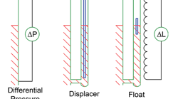
Figure 1 shows a schematic of these devices installed for measuring liquid level. The differential pressure device is placed directly on the vessel. The displacer and the float are put in a stilling well attached to the vessel. The intent of the stilling well is to keep streams entering the vessel from directly hitting the measurement device.
A differential pressure measurement converts a pressure difference into a height of liquid, h, assuming you know the density difference between the liquid and vapor:
h = ΔP/g(ρl – ρv)
where g is the gravitational constant.
In most applications, the density of the liquid is far higher than that of the vapor. Hence, the vapor density often is ignored. However, in some cases, the vapor density can be important. A displacer doesn’t measure pressure. Instead, it measures torque, τ, generated by buoyant force.
Figure 1 -- Methods rely on different variables to come up with a reading.
The displacer is a modern application of the phenomenon that led Archimedes to exclaim “Eureka.” As the liquid level increases, the displaced liquid appears to make the displacer weigh less. This weight change equals the weight of the displaced liquid. If the density and cross-sectional area of the displacer are known, the change in torque directly translates into liquid level.
Both the differential pressure device and displacer measure a physical variable that requires a value for density to convert the measurement into a level. As long as you use the actual density, the measurement is accurate. If the density assumed is wrong or changes, then the level measurement is inaccurate. Assuming too low a density will give a level less than expected while assuming one too high will lead to the opposite result.
Two extreme cases deserve mentioning.
In foams, densities may be dramatically lower than expected. The foam level may be many times higher than the liquid level. Foam can end up in vapor lines and cause significant downstream problems.
The second extreme case is if the actual density is lower than the assumed density and the liquid level goes above the span of the instrument. In such cases, a level instrument may continue to show a liquid level less than 100%; any level changes calculated from the instrument reading are due to density changes in the liquid, not level changes in the vessel. This was a small, but real, contributing factor to the infamous BP Texas City refinery disaster on March 23, 2005. Operators saw changes in level but the liquid level actually was well above the displacer. The changing level reflected falling liquid density as the tower heated up.
Texas City brings up a second point about displacers. They are not the same as floats. The buoyant body in the torque displacer shown doesn’t move very much. It isn’t floating on the liquid. In contrast, a float eventually will reach the top of the range, even if mis-calibrated.
Figure 1 also shows a float — in this case, a magnetic float without direct contact between it and the sensing element. The signal going to the control system is a direct measurement of the float’s position, which isn’t necessarily the same as the liquid level. The float’s submergence will change depending upon the liquid density. The lower the liquid density, the more the float will sink into the liquid, and vice versa.
Many people confuse displacers with floats. Indeed, one source of misunderstanding in Texas City was lack of appreciation of the differences between these two devices. I’ve gone into some detail about these differences in a previous column, “Interpret Level Readings Right,” but it’s worth briefly reviewing them.
Changes in levels reported with changes in liquid density differ dramatically between these instruments. The error in level reading with changes in density for the differential pressure measurement and the displacer is a percent of the level. For differential pressure and displacer measurements, the reading shifts by a percent of the reading.
In contrast, with a float, errors in readings are a percent of the float dimension. A short float would have small errors. A longer float would have larger errors. Errors in density cause an offset in level readings. The measurement is off by a fixed percent of range set by the float dimension independent of the level reading.
The most effective plant engineers understand the physics of what’s being measured by the instrument. They know how this gets converted to common control room readings. And they grasp how to use this knowledge to troubleshoot and run the plant better.
BM Shah, a chemical engineer in Navi Mumbai, India, wrote Chemical Processing to tell of his success with solving a level-measurement problem at a petrochemical plant. Here is his story:
While working at an oxo alcohols unit in a petrochemical plant in India, there were frequent problems in measuring level in a storage vessel containing high molecule weight phosphine.
This chemical is one of three components of a complex liquid catalyst used to convert propylene into N- & I-Butanols and 2-Ethyl Hexanol in the presence of hydrogen and carbon monoxide (synthesis gas). The phosphine is solid at ambient temperature and liquefies above 50°C and is very poisonous in its nature. Full-body overalls, gloves and a facemask are required while handling it during operation or sampling. These coveralls had to be burned after a single use to avoid any human contact. Due to this nature, maintenance of any kind, including that for level measurement like DP transmitters, was considered risky and had to be avoided. This situation presented many problems; it was difficult to know the inventory of the chemical at any time to determine the consumption of this expensive chemical for accounting purposes.
Problems in level measurement were due to the solidification of the chemical in narrow vessel nozzles connecting to the DP transmitter and normal level gauges. Steam tracing and thermal insulation around these nozzles was not effective in keeping the chemical in liquid phase so that level could be accurately measured. These problems were aggravated during steam outages, unplanned shutdowns or during major plant maintenance. The chemical would solidify and would take days and a lot of operator time in addition to cost to liquefy the chemical in DP transmitter/level gauge nozzles. Normal purged type level measurement also failed due to the chemical solidifying in the purge pipe during steam outages, taking days to liquefy again. Sometimes it was required to empty the vessel, a very hazardous operation, to de-choke the instrument nozzles.
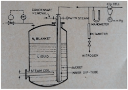
This challenge was met, and it was decided to use a back-pressure type level measurement setup as shown in the figure. Nitrogen is used instead of air as the purge gas for this organic chemical application. The major change/modification was to use the dip pipe (tube) for nitrogen purge as encased in a jacket pipe to which steam is passed for keeping the dip pipe free of solidified liquid. This jacket also served as a heater for the liquid and uniform heating for the entire vessel. When steam is not available, liquid solidifies in the vessel and in the dip pipe but easily converted to liquid phase when steam returned and the level measurement came back into operation without much difficulty and delay. (When the vessel is not vented/open to atmosphere, PC is provided for maintaining a constant pressure in the vessel).


