Chemical plants often must reduce the size of materials to create dramatically greater surface area of particles to improve processing. Indeed, many operations require pulverized or fine feed materials. Providing suitable materials may call for multiple crushing, milling and pulverizing stages. The necessary size reduction equipment frequently is massive, expensive and energy intensive. Moreover, such units suffer unavoidable wear and tear that incurs substantial operational and maintenance costs. Therefore, it’s crucial to select the most appropriate, efficient and reliable units.
Optimized mill or pulverizer performance is a prerequisite for ensuring the best efficiency and performance in subsequent processing units. At many plants, mills and pulverizers form the heart of the processing unit. Often, the root causes of out-of-spec products, poor performance, inefficiencies or frequent shutdowns lie with the mills or pulverizers. Unfortunately, such issues usually result because the teams responsible for design, operations, etc., underestimated the importance of size reduction equipment and didn’t pay adequate attention to such units.
There are three basic types of size reduction:
1. Crushing, in which material usually is forced between two machine elements;
2. Impaction, in which equipment components or an outside force hit the material; and
3. Attrition or grinding, in which rubbing or friction reduces material size.
Fineness is an indicator of the quality of the mill or pulverizer action. It denotes the percentage of a milled or ground material that passes through a set of test sieves usually designated by specific sizes — e.g., 50, 100, 200 and 400 mesh (equivalent to 300, 150, 75 and 40 microns, respectively). For example, a specification for pulverizer performance may require more than 70% of material passing 200 mesh (75 microns) and more than 98% passing 50 mesh (300 microns).
Figure 1. A compression mechanism such as a spring applies pressure to rollers to perform grinding.
Many types of mills and pulverizers are available. Proper selection, design and operation requires considering numerous characteristics and factors such as capacity, effects of moisture content, material sizes, air/gas inlet details, fineness of produced material, outlet specifications, environmental emissions, etc. So, it’s common to find that poorly performing equipment was selected with minimum attention to details and installed carelessly. However, you can take steps to quantify, monitor and improve the operation of size reduction units such as crushers, mills or pulverizers.
Fine Mills and Pulverizers
These often are located close to processing units because moving pulverized materials over long distances usually is difficult. Pneumatic conveyers, pneumatically operated piping systems and others methods can transfer fine or pulverized materials but they are expensive and hard to operate. So, it’s best to keep the transfer distance to the absolute minimum. Often, materials to be milled are transferred by conventional conveyers to bunkers (or hoppers) close to processing units and then passed by feeders to mills (pulverizers) located somewhere below the bunkers. Milled materials then go a very short distance to bins near the processing unit; sometimes, the fine materials directly feed into a processing unit.
You usually should arrange mills/pulverizers to enable doing maintenance and replacement of internal parts and other components subject to high wear without removing the units from their foundations. This demands great care not only because they are near the processing unit but also because mills/pulverizers include auxiliaries and accessories such as acoustic enclosures, lubrication system, etc. and usually require local platforms, walkways, stairs or ladders.
Fine mills or pulverizers often come as standard models, with multiple units used to provide the necessary capacity. For instance, one manufacturer offers eight models covering a 150–800-kW-rated power range, with each model around 20–30% larger than the preceding one. Plants commonly opt for “n+1” or “n+2” arrangements. The one or two spare/standby machines also can be used to cope with harder or more difficult feed materials that reduce the milling capacity of machines in operation. For instance, a large processing unit with five operating and two standby mills sometimes puts all seven machines to work for harder-than-rated feed materials.
Fine mills and pulverizers usually are medium- or high-speed machines. This mandates robust components, particularly rotating parts and those associated with them, that can safely and reliably withstand all acceleration forces normally expected for such high-speed machines. Many rotating parts also require anti-erosive and anti-corrosive features to contend with the considerable wear, erosion, impact, corrosion and abuse that occur during milling. All these requirements, which sometimes conflict, make design, manufacturing and operation more challenging. The housing for a fine mill is difficult to design and build because it demands many features such as air-tightness and robustness, etc., as well as internal lining with anti-erosive material to minimize erosion and wear. Carefully consider appropriate anti-wear measures; otherwise, expect to replace critical parts every few months.
Fine mills that run at high speeds require a special lubrication oil system. Such a system should include two oil pumps (one operating and another standby), a suitable filtration system and an appropriate oil cooler set; it should function reliably in the worst possible conditions such as maximum operating temperature, maximum load, etc.
Condition monitoring of mills and pulverizers usually focuses on vibration and oil analysis; the oil analysis may involve many different sub-tests such as particle count, viscosity measurement, total acid measure, condition of oil additives, sediment in oils, etc.
Each mill needs a suitable classifier to ensure the fine materials supplied to the subsequent processing unit are of requisite fineness. Often, it’s desirable to permit an operator to adjust the classifier to vary the fineness of the materials delivered from the mill/pulverizer; in such cases, the design should enable such adjustments during the operation.
A pneumatic conveyor or similar system often transfers the fine materials to the processing unit. Any pneumatic conveyor is a challenge, demanding great care in design, installation and operation. In many fine mills, air/gas moving through the unit carries the pulverized materials out of the mill — so, automatically maintaining a specific air-to-material ratio for any given load is necessary. Many downstream applications require dry pulverized materials; in such cases, you must adjust the temperature of the air entering the mill according to the detected moisture in the feed to evaporate all the surface moisture within the mill. In addition, it’s sometimes necessary to mix and blend materials during milling.
Selection And Application
As already noted, a variety of mills and pulverizers are available. They differ in design, structure, characteristics and performance. Each machine and method has its own features, application range and special considerations. In choosing a mill, you should take into account many factors such as the properties of the feed materials, product requirements, capacity, etc. Providing hard guidelines on mill selection is difficult because each application poses its own issues and each machine has its own characteristics and optimum performance range. So, it’s extremely important to check for references of successful operation in a given service.
Impact mills. These come in a range of designs that usually rely on high speed components (such as hammers) and high energy impact of these components with materials or materials with each other. They are widely used after crushers for further size reduction or before the fine milling and pulverization. As a rough indication, the lowest size usually achievable by impact mills is around 0.1 mm. They traditionally have dealt with relatively soft materials such as limestone, phosphate, gypsum, shales, coals, etc. However, improvements in designs and metallurgy have made them suitable for a wide range of materials and applications. They have proven a very reliable and efficient option for conventional size reduction and also have handled other services such as combined grinding, blending and grinding/drying.
Ball mills, tube mills and ring-ball mills. A ball mill consists of a horizontal revolving cylinder containing a charge of tumbling or cascading balls, pebbles or rods. As a very rough indication, ball/rod charge may occupy 25–50% of the total internal volume of the mill. The length-to-diameter ratio of such a cylinder usually is between 2:1 and 3:1. Ball mills can perform wet or dry grinding. The wet operation usually takes place at relatively lower speeds than dry ones and discharges a slurry with fine materials. These mills also can carry out blending. Ball mills have many key advantages over other mills. Overall cost of installation and operation is low; they suit wide ranges of applications such as batch or continuous operation, or open- or closed-circuit milling. They also can handle a broad range of materials with all degrees of hardness, compositions, etc. Ball mills come in numerous and diverse designs, with balls and liners available in many different materials. They can be used for practically anything from soft to hard materials and wide ranges of physical properties, corrosion, erosion, etc. The many designs and varieties of such mills make it difficult to generalize about reduction capabilities; as a very rough indication, specially designed ball mill systems can achieve 40 micron or even lower particle sizes at the discharge.
A tube mill is a rotating cylinder with a length-to-diameter ratio of around 4:1 to 5:1 used for fine pulverization. A tube mill often is assumed to achieve finer materials than ball mills. Many tube mills operate wet: the material mixed with a liquid (such as water) is fed into the chamber from one end, milled and discharged from the other end as slurry.
Both ball and tube mills are categorized as relatively slow speed mills. Like many other mills and pulverizers, they include liners to protect against wear. Two main wear parts in these mills are the balls (or rods) themselves and the liners. The wear process consumes the balls/rods, necessitating adding fresh ones on a regular basis; the liners require periodic replacement. Innovative designs for some of these mills attract and hold materials to the internal walls, for instance, by magnetic forces (if materials are magnetic). This protects the lining, reducing wear rates while also increasing milling performance.
A ring-ball mill contains a number of large balls positioned between two rings, like a thrust bearing. The lower ring rotates while a set of spring and adjuster assemblies or pressurized rams force the upper ring to press down on the balls. Feed material enters the center or side of the pulverizer depending on the design. As the lower ring rotates, the balls roll over and crush the material on the lower ring. These special mills only are used in specific applications; reference checking is extremely important for them.
Vertical spindle roller mills and bowl mills. A vertical spindle roller mill uses large rollers for grinding. The feed material is gravity-fed through a central feed pipe to a grinding table where it flows outward by centrifugal action and is ground between the rollers and table. Primary air/gas for material transport enters a windbox plenum underneath the grinding table and flows upward through a swirl ring having multiple sloped nozzles surrounding the grinding table. The air/gas mixes with pulverized materials in the grinding zone and carries them to discharge. Fine materials exit the discharge section through classifier while oversized particles are rejected to the mill for further grinding.
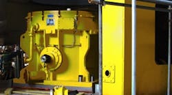
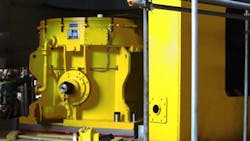
A bowl mill (Figure 1) is similar; it also relies on multiple rollers (tires in some applications) to crush materials. Two common variants are high-speed and medium-speed bowl mills. In high-speed units, the planetary gearbox used to increase the speed is especially critical. Selection, installation, operation and maintenance of such a gearbox demands great care. It should be rugged and reliable, and also easily removable for maintenance. A sealing arrangement is necessary to prevent entry of dust-laden air into the gearbox. Many unscheduled shutdowns or failures stem from bearing issues or oil-related problems. Thrust bearings deserve particular attention because they usually are vulnerable and limited in capacity, and often have relatively low margins and safety factors. The surface of the bowl should be lined properly with suitable wear-resistant materials.
A common mill design employs three grinding roll assemblies; these often use tapered roller bearings. Stop bolts support the system and allow adjustment of the clearance between roller and bowl. Compression springs or another compression mechanism mounted above the roller assembly apply pressure for grinding. An internal multivaned classifier with externally adjustable vanes is connected to the mill discharge.
Materials enter the center of the bowl through an inlet chute; centrifugal force pushes the materials towards the periphery. Meanwhile, the rolls exert the required grinding pressure. The primary air supplied to the mill side moves up through the vanes around the bowl. The air is directed toward the center of the mill, causing recirculation through the grinding area of materials rejected by the classifier. The air lifts the fine materials and moves them to the classifier through the vanes.
Vertical spindle roller mills and bowl mills initially were developed for soft materials; specially designed variants can handle harder materials than those milled in traditional designs. Units can produce fine, pulverized particles in sizes below 40 micron; 30 micron or even smaller particles are possible in certain applications. With proper mill design, metallurgy, speed, mechanical details and operational parameters, special versions of these mills can reliably produce micron-fine pulverized particles. Use of a dynamic classifier, which consists of a stationary angled inlet vane assembly surrounding a rotating vane assembly (or cage), can enable discharge of such micron-fine particles with a narrow particle size distribution.


