This Month’s Puzzler
OSHA is investigating us after an incident involving our phosgene reactor. We make a ketone in it by adding phosgene to dimethyl aniline (DMA) using ZnCl2 as catalyst and toluene as solvent. The process consists of a reactor, condenser, receiver and 4%-caustic scrubber.
Normally, we use recycled toluene. However, on the night of the incident, operators found the toluene was contaminated with byproducts, trace water and hydrochloric acid. So, they added fresh toluene to the reactor after purging the vessel with hot nitrogen.
As part of the startup procedure, they sent phosgene to the reactor to eliminate any water present. The operators didn’t see any temperature rise, which would have indicated water was present. So, they added more phosgene as well as DMA to the reactor, and then heated it to 150°F with hot water and steam. Instead of rising steadily, the temperature suddenly climbed to over 250°F before the pressure control valve went to 100%. Shortly after that, the pressure safety valve opened. Our crew sheltered in place; tests show no phosgene was released. However, OSHA is involved because an operator near the scrubber was hurt when the flange close to the condenser leaked. Our investigation indicates an operator likely was to blame for the incident. Do you agree? What do you think caused the event? Can you suggest any process improvements?
[javascriptSnippet ]
What Procedures Are In Place?
To begin with, there is not enough information in the puzzler to actually solve the problem. A plant’s safety culture is a microcosm of living interactive personal relationships that are hard to quantify. The first thing to look at is the fact this incident falls outside of normal operating conditions: toluene was found to be contaminated. So this is an abnormal operating condition, by stating such we can now look to see if there are procedures in place to handle the upset condition. Is there a standard operating procedure for adding fresh toluene to the process? If yes, does it cover reactor parameters for using phosgene as a desiccant? Does the procedure have parameters (high/low/emergency stop) for when to take emergency procedures?
Your situation looks as though the operators mixed normal operation procedures with abnormal operational conditions, producing an unplanned pressure event. As far as an operator being responsible for the incident, you have not provided enough data (length of time in job, training records, past plant history, standard operating procedures, etc.) for that decision to be made.
If I were investigating this incident, I would find out how many times this condition of contaminated toluene has happened before, and what incident procedures were used in the past. If you remove the condition of contaminated toluene from this incident, the incident cannot happen. At the very least, a team consisting of management and operations needs to further investigate this event in a process hazards analysis. Also, there was no mention of safety interlocks on the process system, or whether or not they were in working order.
Rich Ingles, environmental/safety manager
Cornhusker Energy, Lexington, Nebraska
Ponder Three Issues
I am surprised no phosgene was detected. What do you suppose neutralized it? Assigning blame is easy. Finding the root cause may seem easy but isn’t. Let’s take this in order of priority: 1) the pressure relief scenario; 2) instrument failures; and 3) poorly understood chemistry (which, of course, may impact pressure relief). But follow Kletz’s first rule of accidents: Don’t operate equipment immediately following an accident until it has been inspected.
Think strategically — that’s what OSHA would want you to do. Hire a consultant with expertise. More than likely that person will recommend going with a rupture disc in place of a combination relief valve and rupture disc. This is known as the “biggest damn hole” approach. You’ll want pairs of them in parallel. If one disc pair pops, you can switch to the other. Establish a surefire method for identifying which pair of discs is in operation and which is isolated.
Sometimes the first disc of the pair will crack and pressurize the pipe between the two discs. When this happens, you can switch to the other pair while repairing the first disc. For the safety of the maintenance crew, it is best to have two double-block valves with a bleed in between instead of a single car-seal isolation valve. Take care in choosing the valve seals — you want uni-directional/bi-directional seals. Of course, the double-block valves should be car-sealed open. Refer to: https://xa.yimg.com/kq/groups/3862917/1234089597/name/DBB+vs+DIB.pdf.
As part of the pressure-relief-scenario review, consider the size of the condenser receiver and its vent. Also, evaluate the vent lines for liquid condensation; condensation can restrict vapor flow, especially if there are horizontal sections that could act as traps.
Now, let’s consider the instrument failures. Some of these are self-inflicted — such as the location of the active temperature element, an RTD I assume, in the middle of the tank level. It seems that the RTD was supposed pick up a temperature rise in the liquid if the test phosgene reacted with water. The temperature didn’t rise because the vapor acted as insulation. (As a rule of thumb, vapor has one-tenth the liquid conductivity.) The RTD should be located at the bottom of the reactor. If you haven’t got a nozzle, I suggest putting the sensor in the suction pipe of the reactor pump where the water would be expected to accumulate anyway.
Other “instrument failures” may be due more to psychology than to design errors. Perhaps the production department has become lax in interpreting and responding to these instruments. Review the alarms before installing new instruments that will be ignored. I noticed that the receiver and scrubber have temperature indicators — although temperature lags are a bother, these could be useful in detecting trouble.
What is puzzling is how the operator who was supposed to partially fill the reactor with fresh toluene failed to do so. Was the flow meter partially plugged, causing a high velocity for a vortex type? Was the pump on a timer and the operator relied on this timer? Was the level transmitter measuring correctly? A separate process hazard analysis should reveal the gap between what was done and what should have been done.
Lastly, we come to the side chemistry. You’ll have to define the thermodynamics before you can completely understand the pressure relief scenarios. Also, if the flow meter fouled, it could be because of corrosion. This could stem from an impurity in the raw materials, an impurity created or one accumulated in the toluene. Consider a review of the process steps — don’t forget cleaning operations. Ask two key questions regarding the chemistry: Is there something in the recycled toluene that inhibits potentially dangerous side reactions? Is there something in the fresh toluene that caused a dangerous side reaction? You have some hard work ahead.
Dirk Willard, consultant
Wooster, Ohio
August’s Puzzler
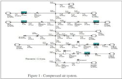
Prior to installing our last filler line, we thought our compressed air system (Figure 1) was adequate. Now, all our pressure-regulating valves (PRVs) are operating near 100% and our actuated valves are having trouble opening or closing. Our dryer is a conventional chiller dryer. The instrument air employs an additional desiccant dryer and a series of water/oil traps. Our plant standard assumes 60-psig actuators and 78-psig air.
Figure 1. Plant now suffers from sluggish operation of actuated valves.
After these problems appeared, I started investigating our plant-wide usage. I found we consume 540 scfm while we’re shut down over the weekend. Some air lines show unusual pressure drops.
Our plant uses a lot of air diaphragm pumps, not only for cleaning up spills but also for moving viscous product around the plant. We keep the product pumps separate to meet cGMP standards. Operators and mechanics seem to connect pumps wherever they want, sometimes even into instrument air lines — much to the chagrin of our instrument engineer. I’ve noticed water and oil dripping out of the air discharge of the air diaphragm pumps.
We’re planning a plant expansion soon and will want to add more pumps and more filler lines. Is there anything we must do to the compressed air system to increase its capacity and pressure?
Send us your comments, suggestions or solutions for this question by July 8, 2016. We’ll include as many of them as possible in the August 2016 issue and all on ChemicalProcessing.com. Send visuals — a sketch is fine. E-mail us at [email protected] or mail to Process Puzzler, Chemical Processing, 1501 E. Woodfield Rd., Suite 400N, Schaumburg, IL 60173. Fax: (630) 467-1120. Please include your name, title, location and company affiliation in the response.
And, of course, if you have a process problem you'd like to pose to our readers, send it along and we'll be pleased to consider it for publication.


