A plant was recovering solvent by vacuum distillation. To avert thermal degradation of the solvent, the reboiler was a vertical falling-film evaporator. The tower bottoms was pumped to the top of the reboiler and allowed to flow down through tubes. The reboiler bottoms was a two-phase mixture that entered the tower bottoms. High-temperature heat transfer fluid was the heat source. Product purity wasn’t meeting requirements. Testing showed the product contained heat transfer fluid. The only connection point between the two systems was the reboiler. It evidently was leaking.
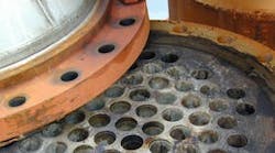
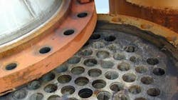
Plant staff removed the upper and lower heads of the evaporator. Figure 1 is a photo of the tube sheet when the upper exchanger head was removed. Many of the tubes obviously were pulling away from the tube sheet.
One of the least expensive options for a shell-and-tube exchanger is to use a TEMA N or TEMA L head (see: "Head Off Heat Exchanger Errors”); these have the tube sheet welded to the shell. To account for thermal expansion, the shell should include an expansion joint to prevent excessive stress from damaging the exchanger or pulling tubes loose from the tube sheet. This particular falling-film evaporator was built without expansion joints. The operating temperature difference between the shell side (heat transfer fluid) and the tube side (process fluid) was 270°F. The exchanger was 15-ft long. So, differential thermal expansion stresses were high. Additionally, the exchanger was subject to thermal cycling. Operating conditions shifted frequently and rapidly. These changes coupled with an anachronistic control system contributed to the thermal cycling.
Figure 1. Many tubes are pulling away from the tube sheet at the top of the exchanger.
Closer examination of Figure 1 shows that most of the tubes in the center have pulled out of the tube sheet. This is a common problem with an exchanger subjected to differential pressures between the shell side and the tube side in excess of the mechanical design.
Tube pullout in exchangers with a hot shell side and a cold tube side typically afflicts tubes nearest the outside of the exchanger, with those in the center having fewer problems. This is the exact opposite of what Figure 1 shows. So is the problem really the lack of the expansion joint?
Localized tube pullout can occur because of flow maldistribution. Areas where hot fluid enters the shell make the shell expand there. This often can result in pullout concentrated on one side of the exchanger. That also fails to fit the pullout pattern seen.
However, maldistribution from the process side — namely, higher rates of cold process fluid down the middle — could cause the problem seen. The falling-film evaporator relied on a single spray nozzle at the top of a conical head bolted to the tube sheet to distribute the entering liquid.
This is an awful system. At best, liquid distribution will be poor. For this system to have any hope of working, liquid rates must be very high and the expected amount of vaporization very low. Typically the only way to get a liquid rate high enough is to use a bottoms recirculation system. This unit doesn’t have bottoms recirculation. The liquid is limited to a once-through flow from the distillation tower.
Examination of the liquid rate showed the spray nozzle was dramatically over-sized. Pressure drop across the nozzle was ~1.2 psi. The spray nozzle needed at least 3 psi to start to form a spray cone. So, the cold liquid largely went down the center tubes of the evaporator.
The center tubes remained relatively cold. The outer tubes rose to the same temperature as that of the heat transfer fluid. The shell plus the outer tubes expanded much more than the inner tubes. The inner tubes pulled out of the tube sheet. Leaks will start well before a tube comes completely out of the tube sheet.
Even if the exchanger’s shell had an expansion joint, pullout still would occur, although perhaps more slowly. The outer tubes were going to be hot and far out-number the inner tubes. Eventually, the inner tubes would have started pulling out of the tube sheet.
For this service, a falling-film evaporator must have a shell-side liquid distribution system that ensures a minimum flow to each tube. The required distribution system is much more complex and expensive than one with a single spray nozzle. In addition, the exchanger should include an expansion joint on the shell.


