Centrifugal pumps are ubiquitous at process plants but many users don't understand how to select and install them. Some strict rules apply and the devil is in the details. So, this article presents some pointers I've gleaned over the years.
Pump selection should start with the system curve. Plants that supply vendors with a system curve have addressed 80% of the pump selection process. Unfortunately, plant-supplied system curves are rare and this leads to excessive costs.
Developing the curve first requires establishing the piping lay out, allowable system pressures and flow rates. Once isometrics are drawn, you can calculate and graph the system curve. The pressure/flow rate plot should represent the changes that flow will experience over the life of the process. This plot is essential for the pump vendor to make a valid recommendation.
The only other plot needed is the range of Net Positive Suction Head Available (NPSHA) the pump can experience. Determining the total NPSHA requires calculating suction-side static, velocity and friction heads.
You should compare these plots to the pump curve the vendor supplies. The intersection of the system curve and the pump curve represents the ideal design point. Comparing the NPSHA to the Net Positive Suction Head Required (NPSHR) will indicate if the pump is a viable candidate.
When selecting between two particular pumps, try to choose the one with the greatest distance between its maximum and minimum wheel (impeller) size shown on the pump curve. Specifying a pump with a wheel diameter nears its minimum means you can't shave the impeller down to adapt to process changes. Installing the largest possible wheel means you can't debottleneck the process later by increasing the wheel diameter, and will need to purchase a new pump.
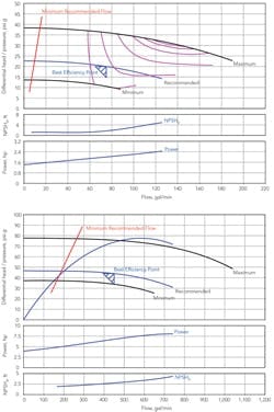
Comparing pump curves requires engineering judgment and experience. Sometimes, though, the choice is clear. For instance, Figure 1 shows curves for two pumps — one, an A-Frame, with a recommended wheel of 9.25 inches; the other, an S-Frame, with a 6.13-inch wheel. Both pumps will operate at the same flow rates when compared to the system curve. However, the larger A-Frame pump has an impeller only 0.25 inch larger than the minimum size for that pump. In contrast, the impeller for the S-Frame is about halfway between the minimum and maximum sizes. Clearly, the S-Frame Pump provides more flexibility to accommodate changes.
A smaller wheel has a higher NPSHR and lower required power draw, but is less efficient. The larger the wheel is, the more efficient the pump if you can operate near or at the Best Efficiency Point (BEP), indicated by the triangular areas on Figure 1. While you shouldn't ignore efficiency in pump selection, BEP operation, shaft length (L) and diameter (D), needed horsepower, NPSHR and process adaptability typically dominate design criteria.

Filtration is an example of a pump running across the curve during required operation. The pump starts at a high flow rate and low head. As the cake builds, discharge head increases. So, it's impossible to design a centrifugal pump to operate at the BEP in this application. This can result in vibration on both sides of the BEP and significant shaft deflection problems.
SHAFT DEFLECTION
Operating to the left or right of the BEP imposes force loads on the shaft. These unbalanced loads cause shaft deflection, vibration and premature bearing and seal failure. Operating to the far right of the BEP also can induce cavitation.
The most effective way to deal with shaft deflection problems is to increase shaft stiffness, which is inversely proportional to L3/D4. The ratio should be less than 60.
Nearly all pump shafts are made of metal. As the pump runs across the curve, it will deflect if ever so slightly. The modulus of elasticity varies, but not much. So, changing material of construction is of little use to increase rigidity.
Shaft sleeves don't add stiffness to a shaft. They are a weight (force) riding on the shaft just like the wheel. They detract from the shaft's L3/D4 and reduce rigidity. Don't use the diameter of the sleeve in the L3/D4 calculation.
Shaft sleeves came into use for one reason — to combat fretting-induced leaks. Packing and lip seals damaged pump shafts. The sleeve was developed so the shaft didn't have to be thrown away. In the absence of packing it has no value. Actually, having a sleeve can increase the cost of a pump because standard shafts must be machined down to accommodate the sleeve.
No sealed pump should have shaft sleeves. Also, use labyrinth seals instead of lip seals.
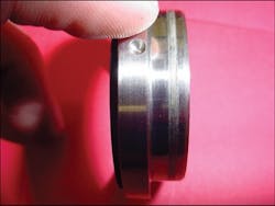
Pumps with stiffness ratios below 60 provide resistance to: several types of cavitation-induced seal or bearing failure; shaft deflection from dead head or running out across the pump curve (empty running); and critical-speed-induced seal or bearing failure. Figure 2 shows fretting damage to seal sleeve caused by shaft deflection.
You must consider 1st critical speed, which is the rpm at which shaft vibration increases dramatically. Shaft deflection reduces the 1st critical speed. It normally significantly exceeds 1,750 rpm for most pumps. However, it can be close to the 3,600 rpm at which "high efficiency" centrifugal pumps run. This is one reason to avoid 3,600-rpm-and-higher pumps. They are vulnerable to critical-speed/deflection-induced premature failures. In addition, double-hung pumps have critical speeds half those of single-hung pumps. Avoid them unless absolutely necessary.
In principle 3,600-rpm pumps are more efficient than 1,750-rpm ones. However, typical centrifugal pumps operate at around 60% efficiency. The higher speed pumps maybe are 5 to 10% more efficient. This only is a big deal if you have a bunch of pumps that are running all the time.
Many pumps start and stop frequently; cranking is the biggest power draw. They run across their curves, reducing overall efficiency. Cranking power and increased maintenance costs can overshadow any perceived economy of high speed pumps. Seal faces will wear out eight times faster for every doubling of rpm. Heat is the enemy.
Whenever possible, specify 1,750-rpm or lower pumps (or their equivalent for 50 Hz). Only select high speed pumps for high discharge head, low flow service. Even then, investigate other pumping alternatives.
Consider how impeller clearance is altered. Some designs adjust the clearance from the volute casing backward, others from the stuffing box forward. Standardize on pumps that adjust the same way. Otherwise, you're setting yourself up for inevitable errors by maintenance technicians.
Impeller adjustment is very important. A pump will lose 1% of its efficiency for every 0.002 inch the impeller-to-volute clearance is out of tolerance. Check the pump's user manual for impeller clearance or contact your vendor.
As a rule of thumb, a typical impeller-to-cutwater clearance is 4% of the actual wheel diameter for wheels under 14 inches, and 6% for larger wheels. Improper impeller/cutwater clearance can damage the pump and will degrade performance.
SEAL SELECTION
Someone at a plant invariably asks: "When environmental regulations and safety don't require the use of seals, why not just use packing?" After all, packing is cheap and easy to use.
However, properly tightened packing draws six times the power of a mechanical seal. Proper tightening requires a light feel of hand and experience. So, most packing is over-tightened. This causes excessive power requirements, and damaged shafts or shaft sleeves that together can waste thousands of dollars per year per pump in electricity and consumables (i.e., sleeves, lip seals, packing, labor, lost production).
A properly selected, installed and operated seal will last until a seal face wears out. This will save thousands of dollars over the life of the seal, even if the old packing was well maintained.
What you need from a seal vendor is progressive cutting-edge designs and responsive technical support. Often the brand isn't as important as the seal representative. Also, always maintain two seal vendors at any one site to service your needs.
Having 24-hour turnaround for seal repair isn't nearly as important as understanding why the seal failed and implementing corrective actions to prevent future failures. Seals always fail for a reason. So, strive to understand and correct all failures; if you don't perform a failure analysis, you'll be changing the same seal very soon. Lack of diligence can lead to unnecessary and expensive downtime.
Seals should last until the sacrificial face has worn out. Consider a seal leaking for any other reason as a premature failure.
Only use cartridge or cassette seals. They are relatively easy to install. Avoid stackable seals. They require the astute hand of an accomplished millwright.
Seal face selection is important. Choose seal faces made of monolithic materials. Pressed faces in metal retainers warp when heated. The difference in thermal expansion between the seal face and the metal retaining ring causes the faces to open and leads to premature seal failure.
When possible, pair sintered silicon carbide (SSC) and sintered carbon (SC) faces. Always specify the highest quality carbon available. This pairing offers the lowest coefficient of friction, which translates to the least heat generation. Again, heat is the enemy.
Using two SSC faces works well when required. The pairing has a higher coefficient of friction than SSC versus SC but provides better mechanical protection from erosion if hard material gets between the two faces. Solids can enter when the seal faces open (e.g., due to cavitation, misalignment and running to dead head), and cause "phonographing" on a face.
A pump that is installed and operated properly will not open seal faces. If inspection shows seal faces have opened, review the installation and operation of the pump to determine why. If SSC/SC faces can't provide sufficient mean time between failures, change to SSC/SSC.
Tungsten carbide (TC), another very hard material, is required from time to time. However, TC/SC face pairings have a higher coefficient of friction and cost slightly more than SSC. So, avoid them unless mandated by a failure analysis.
To extend seal life, specify a stuffing box that can accommodate the largest seal a vendor offers. The greater surface area of the seal faces dissipates heat better, so they will run cooler. Remember, heat is the enemy.
Elastomeric O-ring selection also is important. Strive for a balance between chemical resistance and elastic memory. Typically, higher chemical resistance means lower elastic memory. O-rings with low elastic memory can set, which can lead to premature failure of the secondary seal and leaks.
Always use springs made of a high-nickel alloy that doesn't suffer from chloride stress cracking. Stainless steel springs can fracture from chloride stress cracking — and chlorides are everywhere. The cost difference between stainless steel and high-nickel alloy springs in seal service is negligible in the overall seal price.
API VERSUS ANSI
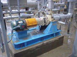
Now, let's consider the difference between API and ANSI frame pumps. API units cost about twice as much as ANSI ones and have lead times that can approach 22 weeks. However, spending more for an API pump often makes good economic sense. API pumps are more rugged in every aspect of design compared to ANSI ones (Figure 3). The shafts have smaller stiffness ratios, the bearings are larger and the stuffing box can accommodate larger seals. Preventing one or two seal failures and the accompanying cost of unplanned maintenance (labor, parts, discarded material, lost production) can more than make up for the price differential.
Another API benefit is the center mount of the volute to its mounting base. This forestalls thermal-growth-induced pipe strain at the flange of the pump.
In contrast, ANSI frame pump feet are attached to the bottom of the volute. Thermal expansion will cause the volute to rise in relation to the pipe and its previous alignment. This will induce pipe strain, which can lead to premature seal and bearing failure.
There are three ways to thermally align ANSI pumps:
1. Offset the "cold" alignment to account for the process temperature.
2. Raise the pump to process temperature, shut down quickly and "hot" align. (This doesn't obviate an initial cold alignment.) If the pump operates over a wide range of temperatures, you may not find a good temperature for hot alignment.
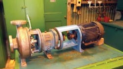
3. Use a C-Frame adapter (D-Frame in Europe) (Figure 4). It will eliminate thermal growth problems and the need for laser alignment. I urge you to use them on all new ANSI pumps and to retrofit existing pumps at your earliest opportunity. I have never regretted the changeover.
A WARNING
Good bearings also play a crucial part. Many foreign "bootleg" bearing companies exist. Their products may carry trusted companies' logos but are low quality knockoffs, like fake Rolex watches.
Beware of low cost discount-label pump vendors, too. The cost difference usually comes from somewhere (L3/D4, bearing selection, etc.). If so, you haven't found a bargain. You've found a costly headache.
Remember, make your selection based on lifecycle cost, not price.
JASON G. LAWS is plant manager for Gulbrandsen Technologies, La Porte, Texas. E-mail him at [email protected].
References
Bloch, H., and Budris, A., "Pump User's Handbook: Life Extension," 3rd ed., Fairmont Press, Lilburn, Ga. (2010).
Karassik, I., Messina, J., Cooper, P., and Heald, C., "Pump Handbook," 4th ed., McGraw Hill, New York (2008).
Mackay, R., "The Practical Pumping Handbook," Elsevier, Waltham, Mass. (2004).
McNally, W., "Centrifugal Pump & Mechanical Seals Manual," McNally Institute, Dade City, Fla. (2008).