Picking a valve for an instrument system means sorting through what may seem an overwhelming number of choices. Just to name a few, there are ball, diaphragm and bellows valves, as well as check, excess flow, fine metering, gate, multi-port, needle, plug, rising plug, relief and safety valves. And each of these comes in many sizes, configurations, materials of construction and actuation modes.
To make the best choice, it's always good practice to first ask: What do I want the valve to do?
Most valves fulfill one of five primary functions -- on/off, flow control, directional flow, over-pressure protection and excess flow protection. Matching valve type to function is the first and most important selection step. It's not unusual to see misapplied valves, such as a ball valve used for throttling flow. In some cases, the mismatch can be catastrophic, say, if a ball valve were in a high-pressure oxygen system. With a source of ignition, the sudden burst of oxygen -- enabled by the fast opening of the valve -- could lead to a fire.
So, here, we'll review the basic types of valves, how they work, what functions they fulfill, and what to think about when choosing one over another.
ON/OFF VALVES
On/off control -- stopping and restarting system fluid flow -- is the most basic valve function. Primary on/off options are ball, gate, diaphragm and bellows valves.
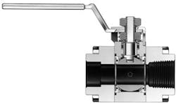
Perhaps the most common of all valve types, ball valves (Figure 1) are designed for on/off control. Quarter-turn actuation starts or stops flow by rotating a metallic ball with a large hole through its center. Straight-through flow occurs when the hole is lined up with the flow path. When the hole is turned 90° from the flow path, flow stops. If you're seeking an on/off valve with quick shutoff and high flow capacity, a ball valve is a good choice. The position of its handle provides a quick indication of whether the valve is open or closed; ball valves are easy to lock out and tag for safety purposes. They are most practical and economical at sizes between ¼ in. and 2 in.
Typically used for process control rather than instrumentation applications, gate valves commonly are chosen for on/off control -- particularly for lines above 2 in. They also frequently serve as the first valve off the process line for instrumentation, often in a double-block-and-bleed configuration. Among the oldest types of on/off valves, they usually are specified in general industrial applications, such as large process or transmission lines. Some can exceed 100 in. Multiple rotations of the handle lower or raise a sealing mechanism in or out of a straight flow path. Shutoff is gradual.
Packing surrounds the stem, the cylindrical part connecting the handle (or actuation) with the inner mechanism, preventing system media from escaping to atmosphere where the stem meets the valve body. Valves that seal to atmosphere with metal-to-metal seals are referred to as "packless" because they don't contain soft packing material, e.g., gaskets and O-rings, normally found around the stem in other valves.
All stem seals or packing are subject to wear, which can lead to leakage. Valves with packing require servicing or replacement at regular intervals, although some types of packing, such as the two-piece chevron design, create more effective seals and last longer than others.
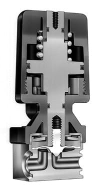
Unlike packed valves, diaphragm valves (Figure 2) are packless. They provide rapid shutoff and precise actuation speeds and, in some cases, also may deliver consistent quantities of process fluid. Diaphragm valves typically are employed in high purity applications. They offer the highest cycle life of any valve type, thanks their highly engineered anatomy. Each valve contains a thin metal or plastic diaphragm that flexes up and down, creating a leak-tight seal over the inlet. This robust valve usually is small, with the largest orifice or internal pathway typically less than 2 in.
Bellows valves also are packless, making them a good choice when the seal to atmosphere is critical and access for maintenance is limited. They frequently are specified for the containment area in nuclear power plants. A welded seal divides the lower half of the valve, where the system media resides, from the upper parts of the valve, where actuation is initiated. The stem, which is entirely encased in a metal bellows, moves up and down (without rotating), sealing over the inlet.
Bellows and diaphragm valves are said to have a globe-like flow path. In globe valves, fluid doesn't flow straight through on a level plane as in a ball valve. Instead, it enters the valve under the seat and exits above the seat. Globe valves have lower flow rates than straight-through-flow-path valves of the same orifice size.
[sidebar id="4"]FLOW CONTROL VALVES
These enable an operator to increase or decrease flow by rotating a handle. Once adjusted to a desired flow rate, the valve will hold that flow rate reliably. Some flow control valves also provide very reliable shutoff, but many turns of the handle are necessary to move from the fully open to the fully closed position.
The most common flow control valves are needle, fine metering, quarter-turn plug and rising plug.
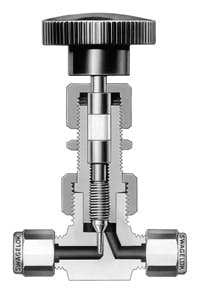
Needle valves (Figure 3) offer excellent flow control and, depending on design, leak-tight shutoff. They consist of a long stem with a highly engineered stem-tip geometry (e.g., vee- or needle-shaped) that fits precisely into a seat over the inlet. The stem is finely threaded, enabling precise flow control. Stem packing provides the seal to atmosphere.
Some designs feature a metal-to-metal seat seal; consequently, needle valves are a good choice for high-temperature applications. However, flow is limited because of the globe-style flow path. Needle valves also suit lighter, less viscous fluids.
For the most precise flow control, consider fine metering valves. Typically found in laboratory settings, these are a type of needle valve with a long, fine stem that lowers through a long, narrow channel. This makes for a pronounced globe pattern, ideal for marking fine gradations of flow. Some fine metering valves aren't designed for shutoff.
Quarter-turn plug valves are economically priced utility valves. Quarter-turn actuation rotates a cylindrical plug with an orifice in a straight-through flow path. Plug valves commonly are used for low-pressure throttling applications in addition to shutoff.
Rising plug valves, like needle valves, lower a tapered element into an orifice to reduce flow. They differ from needle valves in their flow path, which is straight-through rather than globe patterned. Because of the straight path, the valve isn't as effective at providing fine gradations of flow. The rising plug is roddable -- and so it's a good choice if there's a risk of clogging with system media.
DIRECTIONAL FLOW VALVES
A third function of valves is to direct flow.
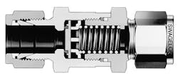
Check Valve Figure 4. Unit prevents reverse flow and can come with
fixed or adjustable cracking pressure.
Check valves (Figure 4) ensure flow in only one direction. In most designs, the upstream fluid force pushes a spring-loaded poppet open, allowing flow. An increase in downstream or back-pressure force drives the poppet back into the seat, stopping reverse flow. Check valves are available with fixed or adjustable cracking pressures.
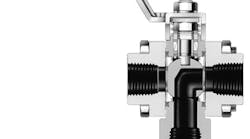
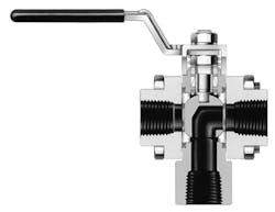
Some ball and diaphragm valves are designed with multiple ports. In most multi-port valves (Figure 5) fluid enters through a single inlet but may exit through one of several outlets, depending on the position of the actuator. Multi-port valves may or may not have a shutoff position.
OVER-PRESSURE PROTECTION VALVES
These devices prevent buildup of system pressure beyond a certain setting. They come in two types: relief valves and rupture discs.
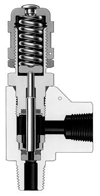
One type of relief valve is a proportional relief valve (Figure 6). It contains a vent to atmosphere that opens when system pressure exceeds a set point. A spring-loaded poppet enables the measured release of fluid. The vent closes when pressure returns to a point below the set point.
A safety relief valve is designed to open very quickly, releasing a large amount of system media. Safety codes require use of such valves in certain applications.
Don't use safety relief and proportional relief valves interchangeably with check valves -- the three serve different functions.
Rupture discs are found mainly on sample cylinders to protect against over-pressurization, which may occur, for example, when temperatures rise during transport. Like relief valves, rupture discs vent to atmosphere. A metal diaphragm bursts when pressure reaches a value preset by the manufacturer. Once activated, the rupture disc must be replaced. A rupture disc is an economical choice where transportation codes require equipping compressed gas cylinders with a pressure relief device.
Multiple-port Valve Figure 5. Some ball and diaphragm valves can direct flow
to one of several outlets.
EXCESS FLOW VALVES
Designed to stop uncontrolled release of system media if a downstream line ruptures, excess flow valves use a spring to hold a poppet in the open position under normal conditions. When excess flow arises downstream, the poppet moves to a tripped position, preventing almost all flow. When the system is corrected, the valve returns to its open position. These valves are available with fixed tripping values.
A GOOD START
Once you have matched valve type to function, you're well on your way to selecting the right valve for your instrument system. However, you still must grapple with many details, including:
• installation issues, maintenance schedules and access;
• safety and code requirements; and
• system parameters, such as pressure, temperature, flow rates and system media.
Ultimately, you'll need to determine:
• valve size and type of actuation; and
• materials of construction (including O-rings and seals), which must be compatible with the chemical composition of the system media, pressures and temperatures.
A valve manufacturer's representative as well as product catalogs and product test reports can be valuable resources in refining your choice.
Keep Five Pointers in Mind
1. Know your application. When choosing a valve, you must have on hand certain pieces of information, including the chemical composition of the system media and the full range of pressures and temperatures the valve may experience over its life. Make sure your valve choice can accommodate these parameters. Don't go with hunches or approximations. Consult the product data.
2. Check for material compatibility. It's possible to have the right valve but the wrong materials of construction. Valves often come in a standard set of materials, but others often are available. Always check the product catalog to identify temperature and pressure ranges, as well as compatibility with different system media (chemicals). When in doubt, consult your manufacturer's representative.
over-pressurization, this valve provides a measured
release of fluid.
3. Factor in the maintenance schedule. Different valves have different maintenance schedules. Your system parameters, including the number of times the valve is cycled, will affect this schedule. Your maintenance team must be able to manage the schedule. This seems like an obvious point but it's often overlooked. Are you willing to service that valve once every 20 days when it's 100 feet in the air?
4. Understand pressure drops. Almost every valve or other component produces a drop in pressure. You must check the cumulative pressure drop, to avoid risks of ending up with too little pressure at a certain point in the line. Every valve is rated with a flow coefficient, Cv, which describes the relationship between the pressure drop across an orifice, valve or other assembly and the corresponding flow rate. The higher the Cv, the lower the pressure drop. Ball and needle valves of the same size will produce very different pressure drops -- very little for the ball valve but significant for the needle valve (or other globe valves).
5. Consider cost of ownership. The true cost is the purchase price plus the expenses of owning and maintaining or replacing a valve over time. To calculate the cost of ownership, you must know how long the valve will operate in your particular system between maintenance checks. Maintenance costs should include replacement parts, labor and downtime. Some valves are much easier to maintain than others; some can be serviced in place, while others must be removed from the process line. Also, given your valve choice, what are the chances of unscheduled maintenance and downtime?
MICHAEL ADKINS is product manager, general industrial valves, for Swagelok Co., Solon, Ohio. E-mail him at [email protected].
