Take Some Basic Steps with pH Measurements
|
Learn more about pH measurement by visiting these articles, books and whitepapers > pH measurement faces acid test
|
Many processing operations depend upon pH measurement. Yet, too often plants find it challenging to get accurate readings. So, we’ll discuss the variety of factors — ranging from the nature of the pH sensor to process conditions — that come into play.
First, though, let’s start with some history. In 1909, Søren Peter Lauritz Sørensen proposed a method to describe the acidity or basicity of solutions1. It’s based on the interaction of two water molecules to form hydronium and hydroxide ions:
H2O + H2O → H3O+ + OH- (1)
A solution is considered neutral when it contains 10-7 moles/L hydronium (protons or H+ ions); he termed this pH 7. The most alkaline solution has an H+ ion concentration of 10-14 mole/L, hence a pH of 14. The scale runs from 0 to 14. At pH 14, the sensor is measuring H+ ions beyond the PPQ level.
How do pH sensors work?
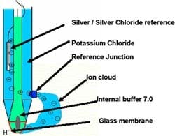
To answer this question, it’s important to understand and recognize the functions of the pH sensor and its parts. Figure 1
The glass membrane responds to changing hydronium ion concentrations to produce an electrical potential proportional to the concentration — this is continuously compared with an internal pH 7 buffer. At pH 7, the electrical potential is the same on the outside and the inside of the glass membrane, yielding a zero potential difference. Therefore, we are measuring zero potential at pH 7. (Broken pH sensors also can give zero electrical potential — so, check for fluctuations in pH to indicate the sensor is actually responding.) In alkaline and acidic solutions, the potential reflects changes in the concentration of hydrogen ions at the outer surface of the glass measuring electrode.
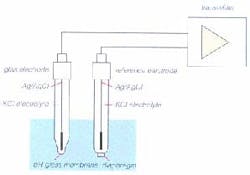
As the difference in hydronium ion concentration builds up junction potential, the alkali metal in the measuring glass transfers the charge onto a silver wire. (Glass, which sometimes is called an amorphous solid or pseudo solid, possesses the properties of an electrolyte.) Figure 2 depicts the electron flow of a pH measurement circuit loop.
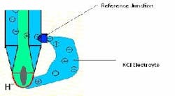
In actuality, most pH probes today use combination electrodes, with the reference electrode and measuring electrode within a single glass body. This pH electrode is immersed in the process liquid and electrolyte flows out from the reference junction and forms an ionic bridge completing the circuit (Figure 3). The voltage ratio calculated between the two electrodes provides the pH value.
Glass electrode. This also is known as the measuring electrode. A special glass acts as a membrane interacting with process H+ ions and the alkali metal ions in the glass membrane. The interaction creates an electrical potential on the glass surface that changes as the hydronium ion concentration changes in the process fluid.
Two kinds of glass membranes are mainly available, ordinary and “B” types. Ordinary glass has cross-sensitivity towards other cations such as sodium ions. In salt solutions the pH may be neutral; however excess sodium ions from NaCl ionization can fool the ordinary glass membrane. The Na+ ions mimic the effects of hydrogen ions. As such, the sensor reads a lower than actual pH. This is common with such membranes in highly caustic fluids and is commonly referred to as sodium ion error.
“B” glass membranes, which contain a lithium impurity, are less sensitive to alkali metal ions. “B” glass formulation can minimize sodium ion error.
Reference electrode. The pH measurement is a half-cell reaction and requires an electrical circuit to be completed. The electrolyte from the reference cell completes the circuit with an ionic bridge. This electrode provides a reference voltage for comparison with the potential delivered from the glass electrode. The electrolyte is pressurized up to 6 bars. Often it’s in polymerized gel form to prevent rapid depletion.
Reference junction. The process fluid and the reference electrolyte interface at the reference junction. The junction permits the electrolyte to create the ionic cloud around the glass electrode to complete the electrical circuit.
Several types of junction interfaces are available; the longevity of a sensor depends upon selecting the proper reference junction. This can be as simple as an open hole allowing electrolyte interface with the process, or can use porous materials such as ceramic, polytetrafluoroethylene (PTFE) or wood, which allow the electrolyte to dilute into the process.
Sensor issues
The nature and care of the sensor and its need for maintenance and calibration pose a number of challenges.
Measuring glass issues. The measuring glass membrane can become dehydrated or can get coated with process material. The glass membrane sensitive to pH changes requires periodic service in many process conditions. To clean, soak it in pH 4 buffer and dab it with a clean cloth. If it doesn’t respond or calibrate, then use hot pH 4 buffer. There’re many other ways to clean a pH sensor; cleaning is application specific. It’s also important to note that deionized (DI) or demineralized (DM) water isn’t necessary to rinse the probe; clean tap water works fine. In addition, don’t store the pH sensor in DI or DM water. Doing so actually will shorten the sensor’s life. When the probe is in DI water, the reference fluid that’s in contact with DI water will equalize its ionic strength. This will deplete the electrolyte — it becomes diluted, resulting in shorter probe life.
Reference electrode challenges. When the reference voltage deviates from 0 mV, an error in pH measurement occurs. Depending on the process fluid characteristics, the reference electrolyte can get diluted (contaminated) through the interface with the process. The rate of reference contamination can be fast or slow depending on the permeability of the reference diaphragm. For example, open aperture reference junctions may get diluted comparatively faster — but also have relatively faster response to the pH changes in the process environment. In extreme cases, where the reference diaphragm is a large disk-type surface, scraping can expose a new surface.
Reference electrolyte contamination. The eluting of the reference electrolyte out of the reference diaphragm into the process to form an ionic cloud can lead to dissimilar ions in the reference electrolyte. When the junction potential is changing due to reference contamination, it will appear as a drift in pH. The solution to this ranges from using a different type of junction material, to multiple junction reference assemblies or a pressurized free-flowing reference/junction.
Pseudo halide ions situation. When reduced sulfur or cyanide is present, with porous or open aperture junctions these pseudo halide ions migrate into the reference electrode, contaminate the reference electrolyte and combine with the elemental silver wire to form silver sulfide. Excessive sulfide ions may form a highly water insoluble silver sulfide coating on the wire. Using double junction reference electrodes (Figure 4) with KNO3 in the first reference chamber will help overcome the sulfide and cyanide ion problems. A potassium nitrate solution prevents the sulfide or cyanide ions from getting into KCl reference chamber.
Solid state sensor. It’s possible to avoid glass issues by opting for a sensor based on the ion selective field effect transistor (ISFET), which was developed in the early 1970s. Such sensors particularly suit food and pharmaceutical processes. However, ISFET technology poses its own set of challenges. The sensor’s measuring surface is reduced to approximately a 2-mm-dia. circle. Processes with high suspended solids can create problems with this limited measuring surface area. Installing the sensor at a 45° angle to the process flow can mitigate this situation.
Signal transmission. Most sensors provide analog mV signals; such signals are susceptible to galvanic interference, which we’ll discuss shortly. It’s possible to avoid such problems by choosing a sensor that digitizes the signal before sending it to the analyzer. Figure 5 shows such a sensor that uses our Memosens technology. These sensors also feature an inductive coupling of the pH sensor and cable, allowing the data and power transmission to travel bidirectionally.
The process environment
Proper sensor selection is the key to long probe life and good performance. Combination pH probes are expected to respond very quickly, almost 90% of a pH step change in 10 seconds. This requires a constant free-flowing and pure reference electrolyte and a hydrated measuring glass.
In choosing a sensor, you must consider process dynamics, conditions and surroundings. Factors to watch out for include:
- coating of the glass membrane
- liquid junction plugging
- fluid velocity
- temperature and pressure of the measured fluid
- abrasion, drying and aging of the glass membrane
- galvanic isolation
- calibration and storage
- hypoionic processes (low ionic strength)
Let’s look at several of these.
Coating. As the sensor remains in contact with process fluid, that fluid starts depositing onto the measuring glass surface. Periodic cleaning of the glass membrane with soap and water will remove such deposits. Automated cleaning and calibration systems are available and may be useful in explosion-proof locations or ones posing health hazards.
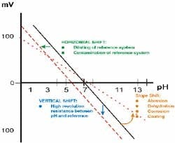
Aging of the pH sensors. A new probe when calibrated will have 0 mV offset at pH 7.0, and a 59.3 mV/pH slope. As the probe ages, both the offset and slope will change. The altered slope may translate into sluggish response to changes in pH. This will call for frequent calibration. Figure 6 explains the aging process of pH sensors and how it impacts the accuracy of pH measurement.
Galvanic interference — the ground loop. A static buildup in the process fluid may produce an electrical potential that affects the mV output of the sensor. This mismatch in potential starts at the pH electrode’s measuring tip and travels through the cable into the pH transmitter’s input circuitry.
A ground loop can cause the following problems:
- an offset from the actual pH reading
- a drift of the actual pH reading. This could be an increasing or decreasing drift and can start and stop at any time
- saturation of the signal to a high or low level, or to a level anywhere in between.
You can confirm galvanic interference by placing the sensor in a plastic or glass beaker of process sample and then grounding the solution to the process piping. If the pH changes by more than ±0.1 pH, a ground loop is present.
Calibration and storage. pH sensors can only read accurately when correctly calibrated. Proper calibration demands known concentrations of buffers and stable temperature and humidity conditions — ideally, conducted in a lab environment by a trained technician. As already noted, don’t store the sensors in DI water. Instead, use 3 molar KCl (saturated KCl solution) at room temperature.
Hypoionic processes. In water purification processes such as reverse osmosis (demineralization) or distillation, water becomes extremely low in ionic strength. Measuring pH on such processes becomes vary challenging due to low electrical conductance. To overcome this situation requires applying external sources of electrolyte to the sensor — reference electrolyte is supplied from an external reservoir into the reference cell.
Troubleshooting pH sensors
The main components of a typical pH loop are the process, sensor, cable and transmitter. These, individually or in combination, can produce problems with measurements. A five-step approach can help pinpoint the source:
1. Identify the problem. Recognizing there may be a problem with a measurement signal is the start of troubleshooting. Process knowledge, measurement history and data trending are key factors in determining if the pH reading is correct.
2. Isolate the problem. In some cases, the application may be the problem. Process conditions play an important role in successful pH measurement. For example, low conductivity water will require a special reference. If the process is associated with sterilization cycles, PTFE may not be a suitable reference junction. Frequent replacement can be a tip-off to use of the wrong sensor. Always document process conditions.
3. Find the culprit component. With one complete working pH loop, interchange components in the order of sensor, cable and transmitter to isolate the problem part of the pH loop.
4. Characterize the problem. If you’ve identified the sensor as the issue, check the area around the reference junction. Inspect the measuring glass. See if there’s any discoloration of the reference fluid. Occasionally a pH sensor can pass quality control testing at the factory and the performance test at the customer’s site but ultimately suffer a short life.
5. Check for galvanic isolation — ground loop. Use the procedure mentioned earlier. A possible fix to the ground loop may be as simple as removing the output wires from the transmitter (for example, the 4–20 mA output) and checking to see if the reading returns to normal. In some cases however, a sensor that digitizes the signal may provide only real solution.
Take some basic steps
Selecting the appropriate pH sensor technology requires understanding the particular process chemistry and conditions, and their impact on the sensor. This will allow you to choose a sensor that will save chemicals and time. The correct sensor will improve production — avoiding off-spec products and waste — and lead to a more energy efficient and profitable operation.
1Sørensen, S.P.L., “Electrometric method of determining hydronium ion concentration,” Carlsberg Laboratories, Copenhagen, Denmark (1924). (Sørensen’s original paper.)
Bhupen R. Patel is business manager, analytical products — Midwest, for Endress+Hauser, Inc., Greenwood, Ind. Fred Kohlmann is Sussex, Wis., based business manager — upper Midwest for Endress+Hauser. E-mail them at [email protected] and [email protected].


