Ejector-driven vacuum systems come in many configurations. However, they basically fall into two categories, wet or dry. Wet systems use an exchanger upstream of the first ejector to condense material and remove the liquid formed, thus cutting the load on the vacuum ejector. (They are called wet systems because often water is what’s condensed.) Condensation pressure required on the process side against the available cooling medium temperature limits wet system performance. While larger, dry systems are required for many low-pressure vacuum services.
Use of a precondenser demands careful analysis of the entire system, as one site clearly learned. The plant used n-methyl-2-pyrrolidone (NMP) as an extraction solvent, with NMP recovered via steam stripping in two flash towers under vacuum. The vacuum system included a precondenser and condensate drum upstream of the first ejector stage to minimize ejector installation and operating costs.
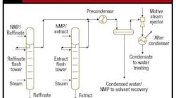
Figure 1 depicts a portion of a simplified process diagram showing the flash towers, precondenser, drum and part of the vacuum system. Water/NMP condensate from the drum goes to drying for solvent recovery. Wastewater from the vacuum system condensers goes directly to water treating.
Figure 1. Stripped solvent went to the water treatment system instead of being recovered as intended.
The plant staff was unhappy with the system due to solvent losses. The extract and raffinate products had virtually no solvent in them. In contrast, the precondenser failed miserably — its duty was so low that no condensate collected in the drum. All the stripped NMP went into the vacuum system and ended up at the water treatment plant.
The rest of the vacuum system worked well, though, believed the plant staff. Vacuum pressure was maintained at 10 torr (mm Hg absolute) at the flash columns without any problem. This should have raised an immediate alarm. Could the vacuum system be working too well?
To simplify the analysis, let’s make some extreme assumptions — that the precondenser contains water without any NMP and that the vacuum-side temperature can actually match that of the cooling water.
Figure 2 shows the saturation temperature/pressure curve for water. The cooling water was available at 95°F. So, using that as the vacuum-side temperature, once the precondenser pressure drops below 42.5 torr, the partial pressure of water is too low for condensation (Point B). Actual operation was 10 torr, which means to get water condensing the temperature must be 52°F or less (Point A).
Figure 2. Too high a vacuum made it impossible for the available cooling water to condense solvent.
The downstream ejector had so much capacity that it pulled down the vacuum pressure to below the water and NMP dewpoint pressure at the available cooling-water temperature. That’s why the NMP ended up in the vacuum system.
The problem wasn’t that the condenser was improperly sized but that the vacuum system pressure was so low that no water-cooled condenser could ever have done the job. As I’ve frequently pointed out, fundamental limits constrain equipment operation. Pressure control on the vacuum system was needed, not a new precondenser.
Ejector pressure control must vary one of the two things that go into the ejector: the load or the driving fluid (steam in this case). Ejectors have relatively narrow operating ranges. Steam-driven ejectors require a specific range of steam mass flow to work. Inside the ejector the inlet steam nozzle size determines the mass flow rate for any given temperature and pressure. Vendors emphasize not to attempt to control the ejector by throttling the steam pressure to the ejector.
However, I must plead guilty here, I’ve put control valves on ejector steam supply to control the ejector. Ejector sensitivity varies depending upon the exact operating point and specific ejector. For a particular case, throttling steam to the ejector may work well enough but don’t count on it — be prepared to vary the load to control ejector suction pressure if required.
In this case, steam throttling wouldn’t work. The required operating point is so far away from the current operation that major changes are needed. Either the load had to be changed or the ejector replaced. If a process operates for years and years far way from the operating point, replacement with a smaller ejector is a very attractive option.
Ejector suction pressure control by changing the load requires either recycling some of the discharge to the suction or adding extra load by steam injection into the ejector suction. Either will work here. Take care with multiple-stage ejector systems. Pick a good recycle location to make sure that non-condensible gas doesn’t choke any of the ejectors. Check them all, not just the first one.


