Process Engineering | Infrared: Get the full picture of thermal imaging | Chemical Processing
A thermal imager may improve your monitoring and troubleshooting of equipment and products. The infrared (IR) camera can supplement or supplant traditional techniques, and provide insights about material storage, equipment heat loss, product moisture content and more.
For instance, plants normally use level indicators to monitor how much material is inside a tank. Yet, many sites increasingly are turning to IR cameras to do the same thing. They want to avoid false indications from level gauges — and the resulting risks of either running out of product or, worse, overfilling a tank that was supposed to be empty. As former President Reagan was noted for saying:
“Trust, but verify.”
Typical thermal images show the contents of the container and give quantifiable verification of the material inside. Users, by applying their knowledge of materials and physics to the thermal differences they see with an imager, can deduce the level of fluid in a tank. Figure 1 clearly shows the liquid level because the tank contains two different materials: liquid and air in the headspace.
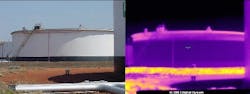
Figure 1. Thermal image clearly indicates the level of fluid within the tank.
Because of that human deductive element, the meaningfulness of the examination depends upon the person’s knowledge and the type of result desired.
Thermal cycling
Tanks located outside undergo thermal cycling. During daylight, they and their contents absorb heat from the sun and the air, as well as from whatever processing might be taking place. During the night, they give up heat to the surrounding air. This thermal cycle and the different thermal capacities of the materials involved affect how accurately a thermal imager can measure product level.
Uninsulated tanks such as the one shown are highly thermally conductive. As night falls, the headspace begins to cool quickly while the liquid volume cools much more slowly. That makes the thermal gradient between the liquid and headspace readily apparent through a thermal imager. Typically the thermal difference is at its maximum two times a day — once in the morning and once in the evening.
At other times, it may not be possible to clearly identify the liquid level with the thermal imager because the liquid and the air in the headspace may approach the same temperature. Reflections from the sunlight during daylight also can make it difficult to observe thermal differences.
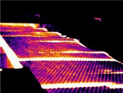
Of course, tanks hold materials other than liquids. Dry bulk materials tend to pile up against the sides and have very uneven levels. Thermal imagers enable you to see these irregularities (Figure 2). Also, many liquids contain particulates that may settle out inside the tank, forming a layer of sediment. This layer generally has different thermal properties than the liquid and, so, often can be identified by imaging.
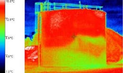
Figure 2. Camera can show highly irregular levels of bulk solids within tanks.
Understanding what the tank is constructed of is important. Many tanks have low-emissivity shiny metal surfaces or insulated walls that make it difficult or impossible to observe internal thermal differences. Being aware of such factors is crucial when evaluating what a thermal imager appears to be telling you. Use caution and apply knowledge!
For instance, look at the reactor image (Figure 3). The color temperature bar indicates that dark blue is approximately 95F and the red at the top of the scale is more than 200F. Notice the dark blue, apparently cool, band where the lid sits on the vessel. What we really are seeing is a very low emissivity ring of stainless steel around the top of this otherwise painted vessel. The painted portion has a much higher emissivity. The bare stainless steel actually is at the same temperature as the painted portions it contacts — more than 160°F, hot enough to seriously burn skin.
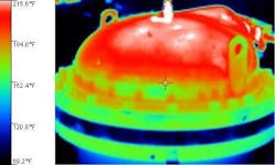
Figure 3. Different materials and surface coatings can mislead unless understood.
Checking other equipment
Of course, heat exchangers, by their very nature of having streams at different temperatures, lend themselves to thermal imaging. An infrared thermal camera can diagnose problems in any manner of heat exchanger.
Thermography also can handle broader process troubleshooting. For example, a process engineer was having difficulty determining why the temperature of a stream was lower than expected. When he sampled and measured the fluid externally, it had the proper temperature.
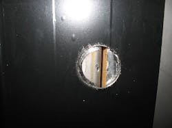
A thermocouple was installed in a stainless steel line for monitoring the temperature of the fluid. Because the piping was all stainless steel, the material surface was too reflective to directly observe the fluid level with the thermal imager. So, to improve emissivity enough to allow camera use, the engineer applied some black electrical tape around the area of the pipe where the thermocouple was installed.
The thermal imager revealed that the pipe was less than one-third filled with fluid. The thermocouple was barely making contact with the fluid, resulting in erroneous temperature measurements. A vapor lock had produced the unwanted headspace.
It is fairly obvious to use a camera to examine furnaces and ovens for heat loss. However, thermography also can offer insights for cooling equipment. For instance, a new process freezer for removing heat from cooked meat patties exhibited numerous areas of condensation on its exterior surface, indicating voids in the insulation system in the walls. The manufacturer drilled holes in the metal sidewalls of the freezer where the condensation was located, trying without success to find the voids. The exterior freezer walls were polished stainless steel which is very highly reflective. The thermographer dried the areas of condensation, placed black tape over them, and then used the camera to pinpoint the coldest spot. He was able to drill a 2-in. hole at the exact location of the insulation void (Figure 4).
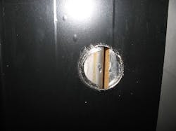
Figure 4. Imaging pinpointed voids in insulation hard to precisely locate otherwise
Broader capabilities
You can use thermal imagers to analyze a great many more things than just temperature, if you understand the spectral and thermal dynamics of your materials and processes. Start by considering how the thermal properties of materials are exhibited in different ways.
For example, imaging often is a good way to check the moisture content of solid products ranging from chemicals to foodstuffs. Consider a cracker baking line where a fairly uniform mass of product passes through an oven. Emerging from the oven, the crackers that contain more moisture appear warmer and those that contain less moisture appear cooler because more moisture translates into slower ambient cooling. A thermal imager can observe the thermal zones of the oven, as well as map the moisture distribution of the product (Figure 5).
Surface moisture content can be measured directly using IR analyzers. When light hits a surface, moisture absorbs IR radiation in the region of 1.8 microns. So IR absorbance correlates with actual surface moisture.
Today, it’s the capability of people, not equipment, that limits application. Thermal imagers rapidly are becoming more economical and easy to use, but the camera is only as good as the person using it.
Take time to examine your processes, understand your materials, and think about how the properties you wish to assess relate to thermal characteristics. Then, having the full picture, you can make the most of thermal imagers.
Emissivity basics
All objects emit IR (thermal) radiation. The intensity of the radiation depends upon the temperature and nature of a material’s surface. At a given temperature, an object that has an emissivity of 1 would provide perfect or so-called blackbody radiation. Of course, in the real world, there are no perfect radiators and materials produce lower emissivities. When a thermal imager observes the thermal radiation from real objects, part of what it sees is reflected from the object’s surface, part is emitted by the object, and part may be transmitted through the object.
L. Terry Clausing, P.E., is an American Society for Nondestructive Testing Level III certified specialist in thermography at TrendFormers, Cincinnati, Ohio. E-mail him at [email protected].