Plant maintenance personnel sometimes choose their steam traps based on the pipe connection size and trap availability in plant stores. For contractors or engineering constructors involved in new construction projects, the choice frequently is driven by cost or delivery factors.
Many makes and models of steam traps are available, but attention is not always given to the differences in features or performance between them. Sometimes plant personnel have the misconception that "a trap is a trap," and all traps operate the same.
Mechanical designs
Mechanical trap operation relies on the movement of closed or open floating objects to actuate the valve. Mechanical traps (or combination pump/traps) fall into one of three classifications:
Float and thermostatic traps, where the buoyancy of the floating object opens the valve.
Inverted bucket traps, where the buoyancy of the floating object closes the valve.
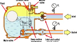
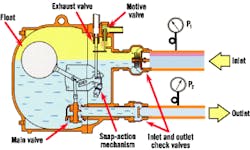
Combination pump and float traps (pump/trap), where the buoyancy of the floating object opens a main trap valve and secondary pressure motive valve. This synchronized combined action allows a higher-pressure vapor to discharge condensate through the main trap valve.
Float and thermostatic traps (F & Ts)
use a sealed spherical or elliptical float that becomes buoyant when the water level in the trap rises, and a temperature-sensing thermostatic element opens to vent air and other incondensables that enter the trap during operation. The two types of F & T traps commonly used are the free float and the lever float.
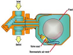
Figure 1. Free Float Trap
The free float trap contains only one moving part ," the float. As its name implies, it has no levers or linkages. No lever mechanism is required to move the valve off the seat. Instead, the float itself is the valve, and the buoyant force of the condensate serves to "roll" instead of pull the valve off the seat as the level of condensate in the trap rises. The rotational movement of the float valve allows precise opening to perfectly match flow requirements.
As the condensate load increases, the float rotates upward against the top side of the valve seat, widening the opening of the discharge area. Under heavy loads, the float completely rises off the seat. It responds immediately to changes in condensate flow or pressure differential.
The rotating action of the float also helps keep the seat clean and allows it to renew its seating surface each time it comes to rest against the seat, eliminating the concentrated wear exhibited by other types of traps. Some free float traps incorporate a three-point seat design to ensure a perfect seal of the float against the valve seat, even in no-load applications. This design is useful with superheated steam conditions. Free float traps also contain a thermostatic element for rapid venting of air and other incondensables.
The float and valve of a lever float trap are attached to the opposite ends of a lever mechanism that pivots on a fulcrum. When the float is in its lowest position, the main valve is closed.
A thermostatic element is incorporated near the top of the trap as an automatic air-venting device. The float becomes buoyant with condensate inflow and lifts the main valve off the seat to allow condensate discharge. Greater condensate flow to the trap means greater float buoyancy and a subsequent higher discharge rate. At near-steam temperatures, the thermostatic element closes the separate vent valve. When the load diminishes, the float is lowered, moving the main valve closer to its seat. The valve closes when the condensate flow ceases.
The principal advantage of the lever float is price: These traps handle high loads at a relatively low cost. On the other hand, continuous modulation of the lever mechanism will wear the linkage if it is not sufficiently designed to avoid such wear. This wear can be amplified by the effect of opposing forces that occur during valve opening and can create more pressure and wear at the fulcrum point.
Figure 2. Combination Pump/Trap
Inverted bucket traps
are old-style density traps that contain an inverted cup-like cylinder (inverted bucket) that becomes buoyant in a level of liquid when subjected to the vapor pressure of a trapped vapor inside the float. The bucket's movement inside the trap is guided by a lever arm mechanism that is attached to both the bucket and the top of the trap. The valve head is positioned on the top side of the lever arm, coming into contact with the valve seat when the bucket is fully buoyant. At the top of the bucket is a small vent hole.
At startup, the bucket is down and the valve is wide open, allowing air to be discharged. As condensate enters the trap and fills the bottom portion of the bucket, any air remaining inside the bucket becomes trapped, causing the bucket to gain buoyancy and close the valve.
The incondensable air must be expelled from the bucket by passing through the tiny vent hole, so air venting generally is very slow.
Once enough air has been displaced by condensate, the bucket loses buoyancy and drops, allowing the trap to discharge. The valve remains open while condensate accumulated at the trap inlet passes through the orifice. As steam reaches the trap, it collects in the bucket and gives it buoyancy, closing the valve. After a certain amount of the steam either condenses or passes through the vent hole, the bucket again drops and opens the valve to discharge the condensate. This intermittent discharge is indicative of cyclic operation.
Inverted bucket traps usually are used as a low-price choice for drip or tracer applications. Unfortunately, they do not vent air particularly well and are not self-draining. Because they require a water prime to close, they are more subject to freezing than other types of traps. They also can lose their prime if subjected to superheated conditions or sudden drops in steam pressure at the inlet.
Mechanical traps operate well against backpressure. The principal limitation of this class of traps is its ability to survive severe water hammer. They should be installed with the buoyant object allowed to rise or fall vertically with the water level inside the trap to open or close the valve. They generally are available in a wide variety of sizes and capacities. Most models are offered with a choice of orifice sizes to operate over a specified pressure range.
Combination pump and float traps.
Many process or heating applications experience a damaging phenomenon known as "stall." A standard mechanical trap design cannot operate and overcome a negative pressure differential. For these applications, a fully synchronized pump and float trap combination, commonly referred to as a "pump/trap," will maintain complete condensate drainage of the system or equipment application.
When the steam pressure in the equipment is less than the return-line pressure, condensate collects in the pump/trap chamber and is forced out through the trap mechanism when the chamber is pressurized. When the pressure in the equipment is greater than the pressure in the return line, the trap section functions as an ordinary trap, and the pump chamber remains almost empty. In this arrangement, the trap mechanism must be a double-seated float type. A high instantaneous flow rate is needed to allow continuous condensate discharge through the trap without constraining the total pump discharge. Ideally, the trap portion should be contained in the pump body to simplify troubleshooting and sizing.
Thermodynamic designs
These traps operate on the principle that changes in static and dynamic pressures caused by changes in fluid velocity through the trap will open or close the valve. The greater the velocity of the fluid, the greater its dynamic pressure and the lower its static pressure. Generally speaking, vapor travels at a higher velocity than liquid, and these traps operate by this difference.
Thermodynamic disc traps
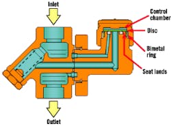
typically incorporate only one moving part ," the valve disc. When the steam system is down, the disc rests on the seat. Air and cold condensate flowing into the trap create a low-velocity static pressure, which lifts the disc off the seat and allows fluids to be discharged.
As the condensate approaches steam temperature, some of the condensate flashes to steam. The higher-velocity flash steam has a lower static pressure; therefore, it lowers the pressure under the disc. Flash steam then enters the control chamber, increasing the pressure on top of the disc. The reduced pressure under the disc and the increased pressure in the control chamber combine to snap the disc shut.
Radiation loss from the top of the trap above the control chamber gradually condenses the steam and reduces the chamber pressure. This allows the inlet pressure to force the disc open, repeating the cycle.
Most disc traps typically do not handle air well, particularly during startup. Air will have the same effect as steam ," to lower the pressure under the disc and increase the pressure above the disc, snapping it shut. Because air is incondensable, the pressure remains above the disc, air-binding the trap. A rough finish usually is applied to the lower side of the disc and the seat lands to create an air "bleed." Unfortunately, this rough finish also detracts from maximum steam sealing..
A combination thermodynamic disc and thermostatic trap design incorporates a bimetal ring thermostatic element that contracts in the presence of air or cold condensate to lift the disc off the seat. This design eliminates the need for a rough finish on the valve disc/seat surfaces, and a mirror-finish seating surface promotes a better seal for greater energy efficiency and life. The disc trap's service life can be further extended with the use of an external air jacket, which slows down the rate of radiation from the control chamber, allowing flash pressure to keep the disc closed longer. Longer closure means a lower cycle rate, reducing disc and seat wear and prolonging trap life.
Thermostatic designs
These traps operate on the principle that a falling temperature will open the valve, and a rising temperature will close it. Valve movement is governed by a thermostatic element. The temperature at this element must fall a certain number of degrees below saturation temperature before condensate can be discharged. In certain designs, the element's controlling temperature is constant; in others, it varies with system pressure.
Balanced pressure traps
are equipped with filled thermal elements. The filling is typically an alcohol/water mixture with a boiling point lower than that of pure water. Two common varieties of balanced pressure traps are available ," a state-of-the-art, fourth-generation sealed capsule and an older-style, second- or third-generation bellows trap.
Figure 3. Thermodynamic Disc and Thermostatic Trap
The sealed-capsule design has a housing constructed entirely of stainless steel, and the valve is fixed to one of several stainless steel or Hastelloy-equivalent diaphragms that overlay each other to create a durable ," yet flexible ," diaphragm.
At startup, the alcohol/water mixture in the element is in the liquid state, and the capsule is contracted to allow air and cold condensate to pass through the trap. As the condensate temperature increases, heat is transmitted rapidly through the capsule housing to the mixture. The condensate begins to vaporize as the temperature in the trap approaches saturation temperature.
The considerable increase in volume generated by the vaporization of liquid raises the vapor pressure inside the capsule. At some point, the internal pressure exerted on the diaphragms becomes greater than the system pressure around it, causing the diaphragms to extend in the direction of the valve and moving the valve closer to the seat. Before live steam reaches the trap, enough vaporization pressure builds up inside the capsule element to close the valve completely.
Eventually, the condensate in the trap cools as the result of radiation from the trap body, allowing the internal pressure in the element to subside. When the vapor pressure is reduced, the diaphragms relax and open the valve, allowing condensate to discharge again, and the cycle repeats.
The top and bottom casings, with the diaphragms sandwiched between them, are welded together to produce a strong, lightweight construction that is highly resistant to water hammer or superheat effects. The shape of the diaphragms should be contoured to match the shape of the bottom casing to give maximum protection from over-extension in the event the element is exposed to excessive temperatures. The use of more diaphragms and Hastelloy-equivalent materials instead of stainless steel maximizes diaphragm life.
The older-style bellows element is cylindrical and has a thin corrugated metal wall made of a highly conductive material for rapid heat transfer into and out of the bellows. The valve is attached to one end of the element, and the other end of the element is fixed to the trap housing. The operation of the bellows element is similar to that of the capsule design: An increase in internal vapor pressure will expand the bellows to close the valve, and a reduction in vapor pressure will contract the bellows and open the valve.
The balanced-pressure element automatically adjusts to changes in steam pressure because the associated change in temperature of the condensate generates the respective vapor pressure in the element necessary to close the trap. Unfortunately, the thin-walled design and proportionately large volume of the bellows-style element make it less effective against severe conditions than sealed-capsule designs. The bellows thermostatic traps are susceptible to damage from fatigue or water hammer, and exposure to superheated steam can lead to overexpansion of the element, causing permanent damage.
Bimetallic traps
incorporate one or more strips or discs consisting of two compatible ," yet dissimilar ," metals with different thermal-expansion rates bonded together. When the bimetal element is heated, the material with the higher thermal expansion coefficient expands faster than the other, causing the element to bend. When the element cools, it returns to its normal state.
By constraining the element within a trap body, the forces generated during heating and cooling can be used to open and close a valve. Bimetallic trap operation and subsequent life expectancy are largely based on whether the trap design uses downstream or upstream valve head construction.
Operation of the bimetallic trap with upstream valve head design is based on both the deflection of the bimetal element with changing temperature and the thermodynamic "suction" effects created by condensate discharge. The element is made up of a stack of opposed bimetal discs to provide maximum head travel. The trap's opening/closing temperature range can be changed by turning an external adjustment screw at the trap's top.
For this design, temperature changes at the element produce opening/closing forces. The effect of backpressure on this trap is minimal, so no significant opposing forces create stresses on the bimetals.
In downstream valve head designs, the valve is on the discharge side of the valve seat, connected to the bimetal element by a stem that passes through the orifice. When hot condensate enters the trap, the element bends away from the orifice, pulling the valve head toward the seat. At a particular temperature, the force exerted by the element is sufficient to close the valve.
Such bimetallic traps are designed to work at sub-cooled temperatures; therefore, an appreciable amount of condensate will be present ahead of the trap during operation, depending on operating conditions and the trap's set temperature. These traps provide excellent results on high-energy-use projects or in situations in which temperature control is needed.
Other selection considerations
Other aspects of trap selection also should be considered ," application, design and operating pressure/ temperature, required capacity with safety factor and piping orientation, to name a few. In addition, a good-quality check valve probably should be installed after any trap that has the potential for backpressure.
Snow is a senior engineer/training supervisor with TLV Corp., Charlotte, N.C. Contact him at (704) 597-9070.
