The efficiency of plants has improved significantly in the post-war period, to the point that, in many cases, equipment and processes have changed almost beyond recognition. Unfortunately, the same cannot be said for the most stalwart of process equipment, which underpins the whole plant operation ," the humble silo (hopper, bunker, etc.).
Very few engineers have a solid grasp of the fundamentals of particulate handling. This situation gives rise to "in-house" storage and handling solutions or a dependence on hardware suppliers to resolve handling issues. Both of these approaches can be time-consuming and costly.
Understanding discharge patterns
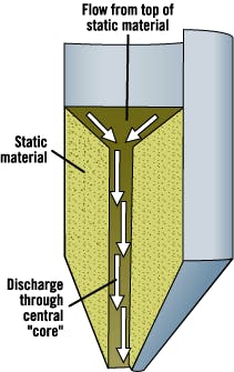
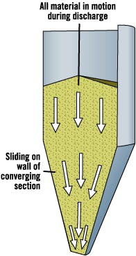
Vessels used to store and discharge particulates into the plant process or packaging equipment must be designed and constructed correctly. Plant engineers should gain an understanding of two basic discharge patterns before purchasing a vessel: core flow discharge and mass flow discharge. See Fig. 1 and Fig. 2.
Figure 1. Core Flow Discharge
Core flow vessels feature convergent wall angles between 45 degrees and 30 degrees.
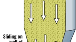
Figure 2. Mass Flow Discharge
A mass flow vessel is designed to encourage material to shear at the walls during discharge.
Contamination is an ever-present issue when materials that could decay and spoil freshly introduced product are handled. Over the years, this type of vessel has spawned its own industry, which produces various types of discharge "aids" to compensate for poor flow characteristics.
In contrast, a mass flow vessel is designed to encourage material to shear at the walls during discharge. The vessel typically features steeper wall angles of greater than 25 degrees from the vertical. Material flows from this type of vessel by gravity alone, on a "first in, first out" basis. Therefore, a mass flow vessel is intrinsically better suited to time-dependent materials.
Because the material is discharged evenly across the cross sectional area of the inventory, this vessel also can reduce the effects of radial segregation, which might otherwise create variations in blend ratios or bulk density values. This type of vessel requires outlet sizes that are typically one-third the size of those required for reliable operation of a core flow vessel, and has the added benefit of operating reliably by gravity alone.
The even draw-down of material also permits a degree of deaeration, or maturing, of product before the product reaches the outlet. A core flow vessel, in contrast, draws the fresh material down the preferential channel, giving rise to flushing or severe bulk density variations.
Both types of vessels have a place in industry, despite their significantly different operational characteristics. For many types of non-time-dependent particulates, in fact, a core flow vessel can be quite adequate.
Anatomy of the problem
Plant operators must spend a little time and effort learning about the characteristics of the bulk material to be handled. Information that should be obtained includes particle size distribution, flow property measurements (internal/wall friction) and compaction curves. Supplementary information relating to moisture sorption isotherms, permeability, segregability and degradation characteristics also might be required.
Many plant budgets do not allow for this level of investigative work, however, primarily because many engineers do not have an adequate understanding of the importance or existence of these types of tests. Instead, some plants transfer responsibility for correct equipment design to the equipment suppliers, based on the understanding that performance guarantees will be forthcoming.
When an investigation into powder properties is undertaken, it usually is limited to the determination of angle of repose, bulk density and median particle size. Or, in some more ambitious cases, a timed discharge through a fixed aperture is undertaken as an index of flowability.
These measurements are adopted almost universally by industry, the main reason being the simplicity of the tests. Although a crude index of handling ability can result from the data, these types of tests cannot yield information that can be used in the design of vessels for reliable operation. All too often "standard" vessel design will be employed in situations that require more careful consideration of the properties of the bulk solid, with poor operational characteristics often resulting.
A lack of understanding of the importance of correct vessel design often can be the downfall of many systems or processes installed as turnkey solutions. In some cases, a contract for a turnkey solution will be bought by organizations with expertise in project management and then subcontracted out. Unless the project management team has a good understanding of the technical challenges to be undertaken, the resulting solution often can require substantial commissioning to iron out problems relating to compatibility and reliability.
Quite often, the resulting procurement and management structure actually can stifle the flow of information between client and equipment suppliers. Instances in which a plant has been designed based on a written breakdown of physical material properties provided by a client are commonplace. Often, these properties bear little or no relation to the material actually being handled by the plant, and serve to generate friction or mistrust between client and provider. It is imperative that both parties ask the right questions and are fully aware of the implications associated with the plant equipment designs.
Turnkey example
A turnkey solution involving hydroscopic material typifies this sort of problem. The plant completed a six-silo installation with the help of an independent contractor. Recently, the contractor inspected the installation. At the plant, hydroscopic material was delivered by truck into a pit, where it then was conveyed to a selected silo via a lean-phase pneumatic conveying line. Each silo had two inlets and associated diverter valves to accommodate a second conveying line that also could be used. Each silo was dedicated to a specific section of the plant.
The company that undertook the provision of the plant was provided with a sample provided by the bulk material supplier of the product to be stored. The sample was found to be free flowing.
On the basis of the sample analysis results, the plant installed an "off-the-shelf" set of silos. The silos included a provision for the introduction of conditioning (dehumidified) air into the cone section through an annular inlet above the silo outlet. The pneumatic conveyor was sized and assembled for the required flow rate and installed alongside the silos.
On paper, everything appeared to be in order. However, several months into operation, problems within the storage silos were becoming apparent. The product was caking into large boulders. It became immediately apparent to site investigators that several interrelated issues were responsible.
A factor that had not been considered by the contractors was the level of material degradation imposed by the routing of the pneumatic conveying line and its operating conditions. A common mistake that many plants make with pneumatic conveying systems is to assume the pipe work can be arranged in a fashion similar to a liquid system. Unfortunately, this assumption ignores the basic fact that the greater the pipeline distance and the larger the number of bends, the greater the pressure drop in the system. The increased pressure drop in the conveying pipeline, in turn, requires higher air pressures at the inlet to the pipeline to convey the material successfully, which means the air velocities along the pipeline also will increase dramatically, resulting in higher impact velocities for the conveyed particles when they encounter bends.
Higher impact velocities give rise to increased pipe wear and increased particle damage. Thus, the particle size distribution of the material arriving at the silo in the example bore very little relationship to the sample on which the design was based.
In this instance, the effect of the particle breakage was twofold. First, the increase in fines content introduced a level of cohesiveness (i.e., reduction in flowability) into the bulk behavior of the material, creating flow characteristics incompatible with the silo geometry (i.e., first-in, first-out discharge was not possible).
Second, the broken particles had their cores exposed, which harbored locked-in moisture. The moisture subsequently was surrendered to the atmosphere to condense on the walls and be transferred to the adjacent particles.
The anticipated benefit of the dehumidification equipment also could not be realized for several reasons. The combined fan/dehumidification unit was severely undersized for the size of vessel, and the annulus had only a single point through which air could be introduced. This setup would have resulted in a preferential airflow through the channel of least resistance rather than dissipation around the annulus.
Closer inspection of the fan in the example case showed it was not only undersized for the required air flow rate, but also unable to develop sufficient pressure to penetrate far enough into the bulk solid.
The plant found itself with a set of silos that was unreliable. In addition, each silo required a $30,000 cleanout to remove deposits.
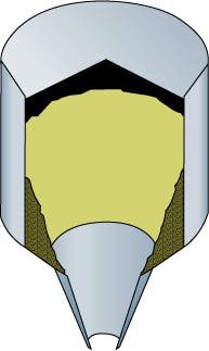
A misunderstanding of the flow properties of bulk solids can lead to the misapplication of various vessel designs. The expanded flow bin shown here had been continually replenished without allowing to drain down to empty. As a result, material accumulated and aged in the upper funnel flow section. The benefits of the mass flow lower cone (acting as a feeder with an effective inlet size beyond the arching dimension for the bulk solid) were negated by the limitations of the operational usage rather than the intrinsic design of the vessel itself. This problem is common and can be overcome through the careful understanding of the properties of the bulk solid and applying that knowledge to the equipment specification and operation.
Problem prevention
How could the problem in the example case have been avoided? Had a risk assessment for the plant's operation been undertaken before the contract was in place, sufficient budget likely would have been made available to undertake some fairly rudimentary work to assess the conveying conditions within the conveying line ," with particular focus on the possibility of degrading the material being conveyed.
A stepped bore pipe could have been considered as a "fall back" option if velocities could not be lowered to a range that would not damage the particles.
Flow characteristic measurement should have been undertaken with a fines-rich sample ," i.e., nominally the worst case ," from which a vessel designed to give first-in, first-out discharge (mass flow) should have resulted. The sizing of the dehumidification unit should have be based on some simple permeability trials using the bulk solid, and the annulus through which the air was introduced should have been subdivided into at least four segments to encourage even distribution of air ," avoiding intrution into the flow path as "mushroom" and other air tappings tend to do.
Conclusion
This article should provide limited insight into a frequently overlooked science ," powder-handling technology. To many plant operators, this subject is considered a "black art;" in reality, however, plants have no reason to suffer from variable product quality or poor reliability. By adopting a scientific approach and applying a holistic view to plant operations, plant personnel will be able to vastly improve product handling and discharge. CP
Farnish is a consulting engineer with The Wolfson Centre for Bulk Solids Handling Technology, University of Greenwich, Lon-don. Contact him at [email protected].
When free-flowing materials are present, the flow channel can expand to intersect with the vertical section of the vessel. This type of discharge pattern gives a "first in, last out" material discharge, which might not present an issue with many materials. However, in situations involving the storage of time-dependent materials, this discharge pattern can be a significant issue, particularly if the vessel is continually "topped up." The vessel shown in Fig. 1 offers the type of discharge pattern seen most frequently in standard "off-the-shelf" equipment. This type of vessel typically will feature convergent wall angles between 45 degrees and 30 degrees from the vertical, and will have an outlet dimension that has been determined by the inlet requirements of the feeder to be installed under the vessel. Once discharge from the vessel commences ," assuming flow can be initiated ," a preferential flow channel forms that extends from the outlet to the top surface of the stored material (in the case of moderately fine materials).


