Utility Systems: Don't Rely on Pot Luck
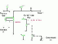
Utility systems often are ignored and underappreciated. Plants take shortcuts in equipment design and installation that lead to process problems. Major issues revolve around sizing, location and control. Getting simple things like steam condensate pots right can dramatically improve plant operations. [pullquote]Sizing, location and control objectives all affect each other. Figure 1 shows a steam condensate pot used on the utility side of a process heat exchanger. The control system varies steam pressure to meet process outlet temperature set point. Level control in the condensate pot prevents steam from blowing into the condensate system. [sidebar id="2"]The steam condensate pot isn't a vapor/liquid separator. Vapor velocity essentially is zero, so disengagement space isn't required. Control span (distance) and response (time) requirements set minimum liquid volume. The level instrument on a condensate pot should be accurate to an inch or two. Many condensate pots work fine with a control span as small as 6 in.; a 12-in. span gives ample control range for most applications. A good control valve can fully stroke from open to closed in as quickly as 5 sec. A 30-sec. condensate residence time for the maximum expected rate suffices for most applications. The 12-in. span and 30-sec. residence-time minimums set the base condensate pot diameter and height. You can have a larger span or a longer residence time if you find that allows a cheaper pot. A rule of thumb is that a vessel with roughly a 3:1 length-to-diameter ratio is most economic for a given volume. Figure 1 shows several other features that merit discussion. The most interesting is pot height. Here, the pot has a liquid level range capable of backing up condensate into the exchanger. This provides a simple method for flooding part of the exchanger bundle. At startup, when the exchanger is clean, or at very low duty loads, steam pressure needed for the required duty may be below condensate system pressure. Condensate won't flow out of the system, stalling the exchanger. One method to deliberately increase steam pressure in the exchanger is to reduce its condensing area by flooding the exchanger with condensate. Resetting the level control point in the condensate pot is a simple method to decrease the exchanger's effective condensation area. Alternative methods use condensate pumps or a second level controller on the exchanger. Having a tall pot eliminates machinery and the need for a second level controller. The figure also shows a large elevation drop from the exchanger to the condensate pot. Minimum height required between the exchanger and the pot must suffice to generate enough static head for the exchanger to run completely drained at maximum condensate load. This provides flexibility for maximum duty or fouled operation on the exchanger. Connection of the vent line near the top of the steam condensing side of the exchanger is a medium level issue. Normally this line has zero flow. It's present to prevent vapor blanketing the condensate pot. Connecting the vent line to the exchanger itself makes condensate drum pressure the same as that of the exchanger. This minimizes the static head difference required between them. If you put the line somewhere else to simplify piping, you must include extra height to generate static head equal to the pressure drop downstream of the connection to make condensate flow into the pot. Two minor points are the temperature cascade to pressure on the steam flow to the exchanger and location of the condensate entry to the condensate pot.
Underappreciated Hardware
Figure 1. Improper sizing, location and control of the condensate pot can lead to significant operating problems.Many installations cascade from a process temperature to flow of steam into the exchanger. Others link temperature directly to the steam supply control valve. Figure 1 shows a cascade of temperature to pressure. In general, pressure instruments are cheaper than flow instruments. Also, the pressure controller provides a direct pressure reading that makes it easier to troubleshoot stall caused by low pressure on the steam. The choice of which system to use often depends upon plant preference. All can work but all have limitations. In the figure the steam condensate line enters the pot below the level control span. Some users have strong opinions about where that line should go — whether below, between or above the level span points. In my experience this isn't an important issue for most installations. Put it where you want. A position within the level control span generally allows a shorter (and cheaper) vessel if it's new. In reusing existing vessels, minimize the amount of nozzle work required. Steam condensate pots continue attract attention because they have so many problems. So, check and recheck them so you don't add to the roster of ones that don't work. Andrew Sloley is a contributing editor to Chemical Processing. You can e-mail him at[email protected].