Getting Your Plant Out of the Twilight Zone
Anyone who has ever watched the "Twilight Zone" knows that the show's common theme centers around strange occurrences that disrupt normal daily activities. Recently, facility engineers at a chemical plant in southern Texas dubbed a recurring ," but seemingly unexplainable ," problem at a control unit the "Twilight Zone."
Problems at the unit included multiple distribution transformer failures, as well as burnout of circuit breakers and electrical connectors. Electric motors were overheating, even while operating within their respective amperage ranges. All of these problems were symptoms of overload. The electrical personnel affectionately called one area the "Bermuda Triangle" because even radios experienced power interference.
When an electrician put away the traditional average response ammeter and traced the problem with a True-RMS (root-mean-square) meter, the investigation began to get somewhere. Initial measurements of phase currents showed values that did not exceed equipment ratings. The neutral conductor was carrying nearly the same amperages as the phase currents, and the phase loads were well balanced.
At this point, attention turned to the recent installation of a medium-voltage variable-frequency drive (VFD) and, as a result, harmonic currents became the "suspects" in this mysterious scenario. Before delving deeper into this situation, however, some background on harmonic currents is in order.
Harmonic currents and VFDs
Today's automated systems have increased productivity significantly and lowered operational costs. However, the expanded use of VFDs has given rise to the occurrence and negative consequences of harmonic currents.
During the past 15 years, an explosive increase in the use of solid-state electronic technology in chemical processing plants has occurred, particularly through the growth in popularity of VFDs. Highly efficient VFDs offer power consumption advantages and increased productivity. VFDs convert 60-hertz alternating current to direct current through switching power supplies that contain rectifiers and often capacitors. The current then is converted back to alternating current with a different frequency.
Diodes located in the incoming power side of VFDs convert three-phase alternating current to direct current. The direct current then is switched by insulated gate bipolar transistors (IGBTs) to create a simulated alternating current.
Because VFDs draw current differently than non-solid-state (electronic) equipment, impedance plays a large role in this drama. Impedance is the total opposition to the flow of alternating current. It is the combined opposition of resistance, inductive reactance and capacitive reactance. Impedance is measured in ohms and is expressed by the symbol "Z." It can be shown in complex notation as Z = R +iX, where R is the ohmic resistance and X is the reactance.1
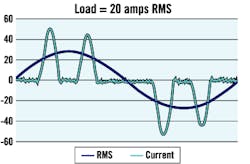
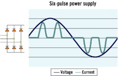
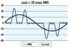
Prior to the introduction of VFDs, non-solid-state applications had a constant impedance drawing current in proportion to the sinusoidal voltage. Electronic equipment such as VFDs changes impedance by switching on and off near the peak of the voltage waveform. The frequencies are modulated to control the motor speed. Switching loads on and off causes quick nonsinusoidal current pulses.
Harmonics are the reflective currents sent back into the power distribution system by switching loads on and off during part of the waveform. Harmonics are described as sinusoidal waveforms operating at frequencies that are multiples of 60 hertz. They are expressed in orders. For example,
second-order harmonics equal 120 hertz (60 hertz x 2); third-order harmonics equal 180 hertz; fourth-order harmonics equal 240 hertz, and so on.
Electronic equipment such as VFDs, computers and copy machines contributes to harmonics. Most solid-state or electronic equipment produces harmonic currents. Just watch the light flicker in your home when you hit the print button on several models of laser printers. It is very important to note that although VFDs are only one contributor to harmonics, they tend to play a greater role in the hydrocarbon processing industry in both low-voltage and medium-voltage applications.
Examples of Nonlinear Loads
What are the effects of high-frequency harmonic currents? As higher-frequency harmonic currents flow through the power system, they can create problems such as:
Overheating of electrical distribution equipment such as cables, transformers and standby generators.
Overheating of rotating equipment such as electric motors by voltage drop.
High voltages and circulating currents caused by harmonic resonance.
Equipment malfunctions resulting from excessive voltage distortion.
Increased internal power losses in connected equipment. This results in component failure and shortened lifespan by increasing the eddy currents that flow in their laminated cores, through increased leakage currents across insulation, and by producing a skin effect in conductors. (A skin effect is caused when alternating current flows through a conductor, and an inductive action forces the current in the conductor toward its surface. The current density is greater at the surface than at the center, and under certain conditions practically no current flows along the axis of the conductor. The result is voltage drop and energy loss.)2
False motor overload trip.
Metering errors.
Power interference on voice communication.
Lower system power factor, preventing effective use.
Inability of automatic transfer switches to operate in closed transition.
Excessive neutral current causing overheating.
Simple light flickering.
High audible noise levels.
Managing harmonic currents
Harmonic currents are here to stay and certainly will increase as technologies advance. Plants can take a number of steps, however, to manage harmonics and minimize their damage.
A certified electrician with a certificate in harmonics can lead the charge
. Ensure the electrician uses a True-RMS meter. Average response ammeters are insufficient because they are accurate only when measuring 60-hertz loads that have sinusoidal current waveforms. They cannot measure the current of nonlinear load accurately.Nonlinear loads draw current in a nonsinusoidal manner and produce reflective harmonic currents that operate above 60 hertz. If an average response ammeter is used to measure nonlinear load currents, readings below the actual True-RMS current might result. The actual current might exceed equipment ratings.
VFD Input Current
Contact your VFD manufacturer to find out what harmonic filters already exist as part of the drive system
. Some VFD manufacturers use DC bus filters (a capacitor between the diodes and the IGBTs) instead of input line reactors to protect the surrounding electrical system from harmonic currents associated with VFDs. Although these filters do a great job protecting the system from harmonics, they do not protect the VFD from power supply problems within the building side of the line.Traditional input line reactors offer this protection, as well as harmonics filtering. The additional protection by line reactors is worth the investment, which is approximately $9 per drive horsepower. The Institute of Electrical and Electronics Engineers Inc.'s (IEEE) recommended practices and requirements for harmonic control in electrical power systems are outlined in IEEE Standard (Std) 519-1992. Although many drives meet these requirements, the drive will no longer meet IEEE 519 if the VFD is not installed under the same standard.
Plants should use specific distortion limits for total harmonic voltage and current distortion calculation and measurement.
For voltage harmonics, individual or simultaneous operation of the VFDs should not add more than 3 percent total harmonic voltage distortion while operating from the utility source, or more than 5 percent while operating from standby generator, if applicable.
For current harmonics, the maximum allowable total harmonic current distortion limits for each VFD should not exceed 5 percent as calculated and measured at the point of common
coupling (PCC). The PCC with the consumer/utility interface is the closest point on the utility side of the customer's service where another utility customer is or could be supplied. The ownership of any apparatus such as a transformer that the utility might provide in the customer's system is immaterial to the definition of the PCC.
Look for the manufacturer's published data on the allowable motor lead lengths for its VFDs
. Long-run motor leads from the VFD can cause insulation failure. Long wiring runs between the motor and control encourage harmonic currents. To solve unavoidable long runs, line reactors or harmonic filters can be placed between the motor and control. Refer to the IEEE "Guide for Specifying and Selecting Power, Control and Purpose Cable for Petroleum and Chemical Plant," (IEEE 1242-1999).VFD Input Current
Several standards should be used when selecting and using motors with VFDs, including National Electrical Manufacturers Association (NEMA) MG1-1993, Part 31.40.4.2, IEEE 841-2001 (2001), and American Petroleum Institute (API) 541 95 3RD.
NEMA MG1-1993, Part 31.40.4.2 states that an inverter-fed motor should be designed for a peak voltage of 1,600 volts (V) and a minimal rise time of 0.1 microsecond for motors rated less that 600 V. This standard always should be specified when using motors with VFDs that use IGBTs. This is critical because voltage spikes as high as 1,600 V are possible when the transistor switches on from the off in the harmonics switching scheme.
IEEE 841-2001 has been updated to include "premium-efficient" motors and applies to high-efficiency totally enclosed fan-cooled (TEFC), horizontal and vertical, single-speed, squirrel cage polyphase induction motors. Included are motors up to and including 370 kW (500 horsepower [hp]), in NEMA frame sizes 143T and larger, for petroleum, chemical and other severe-duty applications (commonly referred to as severe-duty motors). Excluded from the scope of this standard are motors with sleeve bearings and additional specific features required for explosion-proof motors.
It is important to note that most inverter-ready motors have a Class H insulation system rated for 180 Degrees C operation, and for every 10 Degrees C cooler a motor operates, the insulation life doubles.
API 541 95 3RD, for larger motors, covers the minimum requirements for the production and purchase of all form-wound squirrel cage induction motors above NEMA 440 frame sizes (nominally 250 hp and larger) for use in petroleum industry services. It can also be applied to adjustable-speed motors and induction generators with appropriate attention to the specific requirements of such applications. It also gives information for electrical and mechanical design features, insulation systems, accessories and tests.
Several VFD drive manufacturers have introduced a variety of technologies and designs to minimize harmonics in the AC line
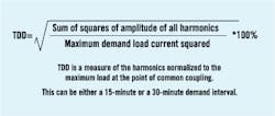
. An important aspect of AC line harmonics to understand is that the total harmonic distortion (THD) is based on a percentage of load, not drive capacity. More importantly, harmonic content, when measured in percent of load, becomes a much higher percentage as load decreases, which is specifically true in variable-torque applications in which the load current changes at the square of the speed. Therefore, it might be more appropriate to refer to total harmonic content in terms of total demand distortion, which considers the system's load capacity, not just the load at the demand point.Some of the new technologies and designs include:
The optional installation of a separate 5 percent impedance input line directly in front of the
VFD ," Because it reduces voltage distortion, it therefore reduces THD. This option is effective as long as the drive load does not exceed 20 percent of the power distribution system's capacity. The stiffer the line (ratio of system, kilovolt-amperes [KVA]/drive KVA), the more likely the drive system will meet THD guidelines of 5 percent or less.
The addition of a DC-link inductor to the drive between the rectifier and the inverter ," This helps to reduce voltage distortion, minimizing THD in much the same way as an external line reactor. Some newer VFDs include a built-in DC-link inductor as a standard feature in models with ratings above 5 hp.
The addition of an AC line inductor between the AC line and the rectifier ," Although this provides slightly better performance than a DC-link inductor, it can be used in conjunction with a DC-link inductor.
The use of 12-pulse configurations, which reduce current harmonics per phase by taking advantage of dual-diode bridge connections ," Instead of current pulses seen 60 degrees apart, pulses are seen 30 degrees apart, reducing AC line harmonics. Drives offering this feature are typically in the 350-hp-to-1,000-hp range and also can be found on commercial compressors that represent a large percentage of the system load.
The addition of synchronous rectifiers on AC drives ," Whether integrated into the drive or added as a separate component, synchronous rectifiers use an IGBT configuration, similar to the inverter section of an AC drive, to replace the diode bridge. By controlling the operation of the transistors in each incoming phase at a high frequency between 10 kHz and 20 kHz, the drive eliminates the pulses normally seen in a diode bridge rectifier. Although this technology to reduce current harmonics per phase originally was designed to allow AC drives to regenerate energy back to the AC line, the benefit of near-zero harmonics has become an even greater benefit.
Total Harmonic Distortion (THD)
A mystery solved
In the Texas plant's "Twilight Zone" case, the engineers discovered a shared-neutral wire configuration within the VFD and surrounding conductors in the control unit that were responsible for the overloads and failures. The neutral wire could not accommodate the increased amperages. These amperages were created by harmonic currents fed by the multiple hot circuits converging on a single neutral wire.
The engineers not only installed an upgraded neutral wire to accommodate these higher amperages, but also added neutral wires for the individual hot circuits. At the same time, they located several low-voltage VFDs without any harmonic filters. They installed harmonic filters and line reactors to filter the incoming voltages on the VFDs. An upgraded neutral wire now accommodates these higher amps.
With minimal effort and expense, the Texas petrochemical plant moved out of the Twilight Zone and the Bermuda Triangle and back into the real world of efficient operating facilities. CP
Graf is a Jackson, Miss.-based industry manager for Applied Industrial Technologies, Cleveland. Contact him at [email protected].
Illustrations courtesy of Rockwell Automation/ Reliance Electric.


