Heat Exchangers: Consider A U-Turn
[pullquote]
A bit of extra surface area in your heat exchangers may enable you to push plant capacity. In certain situations, you can get that area by making some compromises. The Tubular Exchanger Manufacturers Association (TEMA) standards define shell-and-tube exchanger configurations with a three-letter code such as AES. The first letter refers to the front head (tube-side) configuration, the second to the shell configuration and the third to the rear head (tube-side) configuration.
Many heavier-duty exchangers use an S-type or T-type rear head. These head types handle straight tubes and feature an internal chamber with a flange to accommodate the return of the tube-side flow. In these exchangers, you can remove the entire bundle from the shell by pulling it out through the shell. Therefore, the return head must fit inside the bundle.
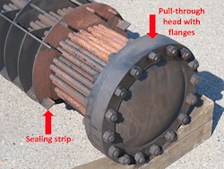
Figure 1 shows a T-style return head. The head’s flange with its bolting circle must fit through the exchanger shell. The flange prevents installation of tubes around the outer edge of the bundle. The smaller the tube bundle is, the larger the tube-count reduction that’s caused by the flange. The higher the pressure of the tube side is, the larger the flange and, so, too, the tube-count reduction. The exchanger shown in Figure 1 has a relatively small bundle with a moderate tube-side pressure rating. The tube-count reduction (and lost area) is relatively large.

Figure 1. The necessary flange limits the number of tubes in a bundle.
Additionally, the distance between the tube and the shell opens up a larger area where shell-side liquid can bypass the tube bundle. Bypassed flow reduces heat-transfer effectiveness. Using sealing strips as shown in Figure 1 reduces the flow bypass but doesn’t eliminate it.
A TEMA U-type return uses u-tubes. Figure 2 shows a u-tube bundle. In contrast to the S- or T-type returns, it doesn’t have a flange. The absence of the flange allows the tubes to be very close to the exchanger shell. On the inside of the tube bundle, the minimum radius possible for the u-bend creates a space between the inside tube rows. Nevertheless, a u-tube bundle has a larger surface area than a S-type or T-type of the same diameter.
The u-tube bundle has other performance differences as well.
First, it rarely suffers from thermal expansion problems. Each tube can expand or contract slightly differently than the other tubes around it.
Second, cleaning the tube-side may be more difficult. One benefit of the S- and T-type heads is that they use straight tubes. So, hydraulic cleaning is straightforward. In contrast, cleaning inside the tubes on a u-tube bundle necessitates cleaning around the return bend.
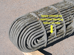
Figure 2. This provides greater surface area but can make cleaning harder.
Third, when a tube corrodes or leaks and is plugged, the amount of tube surface lost is double that of an exchanger with a flanged rear head. However, this shouldn’t be a major consideration. If so many tubes are leaking that the area lost by plugging u-tubes is significant, you should resolve the problem by using more appropriate materials, more stringent fabrication or changing system chemistry (i.e., using suitable additives).
While the u-tube bundle isn’t suitable for every service, such a bundle gives you one more tool to increase plant capacity. Depending upon the flange sizes and exchanger dimensions, you might be able to boost exchanger surface area by 10–15% by using u-tube bundles in place of flanged ones. You can minimize cost by incrementally switching exchanger types when you need to replace worn-out bundles.
