Heat Exchanger: Forestall Fouling-Factor Foul-ups
The overall heat-transfer rate (Uoverall) achieved in a heat exchanger depends upon the overall resistance to heat transfer, which is its reciprocal (1/Uoverall). This, for a unit with a wall between two streams, is the sum of five factors:
1/Uoverall = 1/houtside + foulout + resistancewall + 1/hinside + foulin (1)
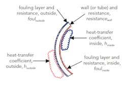
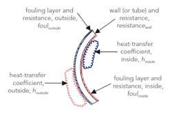
where 1/h is the film resistance for each surface, and the other factors are the resistance of the wall or tube, and the fouling resistance at each surface. Figure 1 shows these factors for a tube in a shell-and-tube heat exchanger. Many users have some sense of the fouling factor likely for most of their heat exchangers.
Of course, some services prompt more fouling than others. For example, a heat exchanger using steam usually has very little fouling on the steam condensing side. In contrast, the process side of a heat exchanger often may foul very heavily. In heat integration services with the process on both sides of the exchanger, fouling may occur on both sides at the same time. Experience also shows that apparently minor changes in exchanger configuration or process conditions can dramatically shift fouling rates from those generally expected for that service.
Direct measurement of fouling resistance is extremely difficult and expensive; it’s rarely done even in research facilities. So, most fouling resistances come from calculations based on exchanger performance. Such calculations give overall fouling but don’t break down each side’s contribution. Experience may allow allocating how much fouling belongs to each side of the exchanger. Often, though, only an overall fouling resistance is stated.
Understanding fouling is important because our calculated fouling levels provide information for exchanger cleaning and maintenance decisions, attempts to mitigate fouling (e.g., additives and operating changes), and purchasing decisions. However, what really is our calculated fouling factor?
Simplifying Eq. 1 by taking the wall resistance as zero and combining the inside and outside fouling, we get:
Fouling = 1/Uoverall - 1/houtside - 1/hinside (2)
Figure 1. Tube in a shell-and-tube exchanger illustrates the five factors that contribute to the overall resistance.
The resultant value comes from subtracting two relatively large numbers from another large number. This concept poses potential problems, as I’ve discussed previously (see February 2015 issue’s “Resist the Temptation”). When using plant data to determine the fouling factor, all errors in the calculation accumulate in the final result.
Plant data are one source of error. We measure the flow rate and the temperatures around the exchanger to calculate duty and provide information for the heat-transfer calculation methods. Are the flow rates and temperatures measured right? We also need the composition of the stream to estimate its physical properties such as viscosity and heat capacity. This becomes especially challenging in exchangers that are partial condensers or partial vaporizers because you really require the rate and composition of each phase.
The correlations we use are another source of error. How good are the correlations for the physical properties needed? In addition, how much scatter appears in the heat-transfer correlations themselves?
A recent analysis I did illustrates how these errors can accumulate. This in- depth study of 60 heat exchangers in multiple units indicated that five had a calculated negative fouling factor after cleaning when their units started up after a shutdown. Another eight had a calculated zero fouling factor.
These 60 exchangers had been in service for more than ten years and had gone through multiple shutdowns. They all received standard commercial handling and cleaning during the shutdown maintenance. It’s highly unlikely they were perfectly cleaned during the shutdown. Also, each one had some amount of corrosion and exchanger wear accumulated over the years. They surely had some fouling resistance present.
The calculated negative-to-zero fouling factors result from data-measurement and physical-property errors as well as correlation uncertainty. In this sample, at least 20% of the exchangers performed better than expected. Due to the physical condition of the exchangers, it’s difficult to say how many performed much worse than expected. Nevertheless, it clearly exceeded 20%.
Fouling factors are useful concepts for monitoring and identifying areas where a plant should take remedial action. However, don’t blindly accept the calculated results — understand the possible errors and how they might affect your operating decisions.


