Waste Gas Recovery Systems Reduce Emissions, Improve Energy Efficiency
Recovering gas that would otherwise be vented or wasted is a hot topic today. Venting less gas reduces volatile emissions that can contribute to ozone and smog formation and global warming potential. Wasted gas sent to combustion just to get rid of it, while not as bad as venting, wastes an opportunity to recover energy and reduce CO2 emissions.
Many sources exist for incentives for CO2 reduction credits. One way to reduce CO2 emissions is to capture the vented or waste gases and use them to displace currently burned fuel.
Contrary to the thoughts of some, the chemical process industry doesn’t have a lot of stupid or lazy people in it. The stupid and lazy went out of business years ago. If waste or vent gas isn’t being recovered, there’s probably a good reason why. In a process plant, the most common reasons include cost and complexity. Incentives being offered help on the cost front. Regulations may also force the issue. Complexity means how much aggravation, attention and risk are posed by the vent gas recovery. Plants want to optimize their process operations, not run at the mercy of utility systems such as waste gas recovery.
One plant I worked with was extremely concerned about liquids in the gas product. They wanted to prevent water condensate from corroding existing fuel gas lines and keep all liquids out of the fired heater and boiler burners. Additionally, they were concerned about freezing up under extreme conditions. Avoiding events like what recently happened in Texas, where nearly the entire state shut down due to extremely low outside temperatures, was a major goal. (See my column “Get Ready For The Next Big Freeze.")
Another major goal was that the waste gas recovery unit would operate as automatically as possible. The only operator intervention required would be pushing the start button. After that, the unit was to be completely independent, operating on its programmable logic controller (PLC). The PLC would include appropriate interlocks to gracefully shut down if needed. Additionally, a minimum on-stream time and capacity was required. The reason for off-stream time was not relevant in most situations. The recovery had to work across an extreme range of environmental conditions, feed conditions and feed compositions. And all of this without operator intervention.
Three technologies commonly remove water from fuel streams: cooling condensation, adsorption and glycol dehydration. Each has advantages and disadvantages. For a variety of reasons, cooling condensation was chosen as the approach.
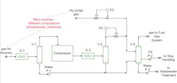
Figure 1 shows a vastly simplified view of the final system. One point that immediately leaps out is the two knockout drums downstream of the compressor after-cooler. This looks odd. Typically, if a drum is sized correctly, a second one downstream is not required. So why use two?
Different elements of gas recovery have different risks. The waste gas recovery has liquids or freezing risks present from two sources. The first source is process conditions. The second source is heat-loss-induced condensation.
Process condition risk comes from the recovered dry purge gases mixing with the compressed waste gas. Joule-Thompson cooling on the purge gas entering was sufficient to cause local freezing. Heating the mixing area mitigated this. The second element was bulk liquid condensation after the mixing. Regretfully, this was a realistic possibility. However, this only occurred when air temperatures were very high. The high air temperatures caused elevated process temperatures out of X-2. Higher X-2 temperatures left more water vapor in the gas at the mix point. With these high exterior temperatures, condensation in the line and fuel gas system does not occur – so it’s sufficient to have a knock drum (V-3) for liquid removal.
Drum V-2 serves a different purpose. V-2 protects against condensation caused by cold air temperatures. If only V-3 is present, gas entering the fuel system is always saturated. If the fuel gas piping cools off, condensation occurs. However, if the water is removed at V-2, it is removed from a smaller gas flow, cold temperature and higher pressure. Then it is depressurized and diluted with the dry purge gas. It is possible to create a gas to the fuel gas system with a < 32°F dew point with this configuration.
Literally, thousands of cases of feed rates, temperatures, pressures and compositions, along with different environmental conditions, were evaluated. Different limits were identified, including adding hydrocarbon condensation and oxygen contamination. The figure shows some very simplified elements of the final unit. The overall configuration does have some weak points. The shutdown cases were projected to occur < 1% of the days during the year. Under these truly extreme conditions, the unit shuts down until operator intervention starts it up again.
Waste gas recovery systems improve energy efficiency and reduce CO2 emissions. However, the spot where one fits into your plant often lies empty for good reasons. Getting a reliable configuration requires extensive evaluation. Nevertheless, proper analysis can find a reliable system that requires minimal operator intervention.
About the Author

Andrew Sloley, Plant InSites columnist
Contributing Editor
ANDREW SLOLEY is a Chemical Processing Contributing Editor.