Improve Your Temperature Measurements
Most process temperature measurements in chemical plants rely upon three critical elements: a thermowell that provides the process containment; a sensor that takes the measurement and translates it into an electrical signal; and a transmitter that converts the sensor signal to a robust communication protocol such as 4–20-mA, HART or Foundation Fieldbus. These elements must work together to provide safe, accurate and repeatable readings.
The nature of the process determines the degree of complexity for each of the three. So, let’s look at them individually.
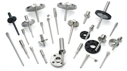
The Thermowell
This device (Figure 1) generally seems the least complex technically. However, more often than not, it actually poses the most problems. These stem from mechanical issues. Therefore, let’s examine how a thermowell works.

Most applications require a thermowell because inserting the temperature sensor directly into the process usually isn’t practical. The sensor normally is encased in a stainless steel sheath, which ideally is relatively thin to ensure fast response. In addition, maintenance technicians may need to remove the sensor from its mount; if it’s a continuous process, they want the ability to do this without losing product containment.
These situations call for permanently mounting the thermowell through the pipe or vessel wall; sometimes it’s threaded into place but usually it’s welded. The thermowell thus becomes part of the product containment but still allows removal of the sensor without interrupting production.
For processes with frequent shutdowns such as batch operations, the uninterrupted containment aspect isn’t as critical. In these situations, the thermowell mount may be attached to the vessel permanently or, alternatively, the thermowell, sensor and transmitter may be a single removable assembly.
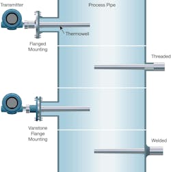
There are multiple ways to mount thermowells (Figure 2) depending on the degree of permanence desired and the severity of the process. High temperatures, elevated pressures and product aggressiveness often demand exotic materials and more robust construction, just as with any process equipment.
Many applications don’t subject a thermowell to taxing conditions. For instance, a thermowell extended into a reactor where the chemistry is benign and fluid movement is minimal usually can operate without problems for as long as any other part of the equipment.
The challenge for a thermowell — or, indeed, for any other piece of process equipment for that matter — is when it’s inserted directly into the path of a moving stream. In most situations, the thermowell is perpendicular to the flow, so vortices form on both sides and create high- and low-pressure areas capable of inducing vibration in the thermowell. Sometimes, the vibrations are tolerable but, in certain cases, they can cause serious harm that leads to fatigue failure.
Deterring Difficulties
Understanding the extent of the problem and properly addressing challenges requires following three critical steps when designing a thermowell installation:
- Prevent problems by utilizing known process parameters, product designs, best practices and calculations. These working together ensure the thermowell is strong enough to stand up to the conditions it will face without failure.
- Suppress the formation of vibrations within the process by modifying the equipment or the process itself.
- Eliminate the need for a thermowell altogether if possible, reducing the risk of process leaks and thermowell failure to zero.
Let’s look at how you can use these three steps when designing an application.
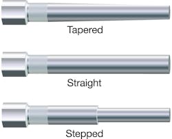
Begin by choosing the right shape, construction material and connection method for the particular process. Specify the correct thickness, length and profile (Figure 3) to withstand the stresses and achieve a tolerable response time. You can get thermowells in all shapes and sizes, and with the wall thickness necessary to withstand a variety of stresses.
Most thermowells are straight cylindrical shapes with parallel sides. This design is strong but has the most material at the tip, slowing response time. A stepped design is thickest at the base for strength and thinner at the tip for better response. It sacrifices some strength overall but reduces drag force in the pipe. A tapered profile provides a compromise — retaining strength and improving response but increasing drag. Making the best choice can be a challenge.
Fortunately, the American Society of Mechanical Engineers has compiled formulas — outlined in its thermowell standard (PTC 19.3 TW-2016) — that you can use to calculate the extent of the stresses anticipated, thus eliminating much of the guesswork. This complex series of calculations requires knowing many details about the specific process conditions but can provide a good prediction of success. The standard covers four test criteria:
- Frequency limit — the thermowell’s natural inline and transverse resonance frequencies must not coincide with the vortex shedding frequency.
- Dynamic stress limit — dynamic stresses must not exceed the allowable fatigue stress limit.
- Static stress limit — the steady-state stress must not surpass the maximum allowable working stress.
- Pressure — the external pressure must not be greater than the pressure ratings of the tip, shank and flange.
These calculations are reliable. However, they assume you have a firm grasp of all the process parameters in detail and can run the numbers for any combination you are likely to encounter in the real world. If your process is stable and tends to operate at the same levels all the time, the exercise probably is manageable. On the other hand, if conditions tend to change, so might the lifespan of the thermowell.
Vibration Issues
The relationship between flow and vibration isn’t linear. Most applications exhibit flow conditions where vibration is minimal. Hopefully these occur at a desirable production level — but you can’t count on this. Unfortunately, instrumenting the thermowell to detect vibration isn’t yet an option.
In real-world situations, a process designer typically will take a stab at performing a few calculations based on known or at least anticipated sets of process conditions. These calculations will identify the kind of profile necessary. The designer then usually will use a safety factor to bolster overall strength; while prudent, this can increase the response time. Adding a thick-wall section that extends outside of the pipe also can create a heat sink, reducing the temperature of the thermowell where it interacts with the sensor. As a result, the thermowell never will reflect the true process temperature, with the reading tending to be low.
Another approach is to mount the thermowell not perpendicular to the flow — for example, in an elbow so the thermowell extends down the middle of the downstream pipe and is coaxial with the flow. Using a 45° tee to position the thermowell closer to the flow axis is another option. If the piping allows these modifications, they can reduce the problems related to wake shedding.
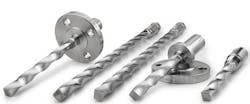
Suppressing vibration at the source often is possible. This generally involves using a thermowell profile designed to avoid the normal wake-shedding problems. Cylindrical, stepped and tapered thermowells all basically are round, allowing vortices to form along the entire length. Emerson’s patented Twisted Square design (Figure 4) disrupts formation of the long vortices and allows them to form on both sides, so they tend to balance and cancel each other. The result is far less vibration — up to a 90% reduction in some cases.
This type of thermowell doesn’t depend on a specific orientation when inserted and reduces the need for excessively thick thermowells and large diameter process penetrations. Moreover, it’s effective and suitable across a wide range of operating parameters, and negates the need for a thick thermowell with its detrimental effects on response time.
A Different Option
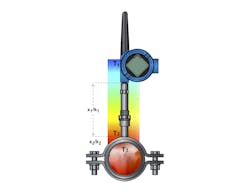
Process conditions — such as a small pipe size, high flow rate or aggressive fluids — may make using a thermowell impractical. Fortunately, a relatively new technology eliminates the need for a thermowell. It uses a sensor mounted on the outside of a pipe and infers the process temperature from the amount of heat transferred through the wall. After calculation of appropriate adjustments based on the thermal conductivity characteristics of the pipe, including material and thickness, along with ambient temperature, the surface-mounted sensor provides an accurate reading of the temperature of the fluid inside near the pipe wall. Anyone planning to use this value should determine the extent to which temperature stratification occurs in the fluid within the pipe.
Because processes at many chemical plants are outside, a repeatable and accurate surface reading requires dynamic compensation, and, therefore, at least one additional sensor to monitor ambient conditions. Such a multi-sensor, surface-measurement approach is now available; Rosemount X-well technology (Figure 5) takes the heat conductivity of the pipe into consideration, as well as continuous monitoring of terminal block temperature, to correct the surface reading. (For more details, see: “Measure Temperature Right.”)
Sensor Mechanics
Many articles (e.g., “Select the Most Suitable Temperature Sensor”) and other references discuss how to choose between a thermocouple and a resistance temperature detector (RTD) as the temperature sensor. So, here instead, we’ll look briefly at the interaction of the sensor and thermowell.
The sensor element itself, as already mentioned, normally is enclosed in a stainless steel sheath. (Various naked-wire thermocouples exist but are rare at chemical plants.) Therefore, heat must transfer through the thermowell and the sheath to bring the sensor element to the full process temperature. Any gap between the two simply slows down the heat transfer — therefore, a tight fit with good metal-to-metal contact is critical.
Some sensor and thermowell combinations effectively are matched sets designed to fit precisely for best heat transfer. Other approaches use generic components; it’s up to the installer to match the two diameters closely. Naturally in these close-tolerance situations, any distortion of the thermowell makes insertion and removal difficult. One solution is to use a looser fit but compensate by adding a spring to drive the sensor against the bottom of the thermowell. A small amount of silicone oil in the bottom of the thermowell also can help facilitate heat transfer.
Transmitting The Signal
In most applications, a transmitter converts the temperature sensor output to 4–20-mA with HART or to a digital signal such as Foundation Fieldbus.
Some users prefer to connect a thermocouple or RTD directly to a control system input. However, this complicates the installation and can impair performance — for example:
- The cabling from the sensor to the input card must match the sensor. Installing a different type of sensor requires changing the cabling.
- Likewise, the input card must match the sensor. Some cards allow for multiple options but only work with temperature sensors.
- The weak signals from a thermocouple or RTD can’t be sent over long distances, and are subject to problems caused by electrical interference.
Adding a simple temperature transmitter close to the sensor eliminates all these problems:
- A 4–20-mA with HART or Foundation Fieldbus signal is much more robust and can be sent longer distances.
- Special cabling or a special input card isn’t necessary.
- Most transmitters work with a variety of thermocouple and RTD types, so changing the sensor when required is very easy.
- Multiplex transmitters can capture data for multiple sensors and send these data back on one cable.
- Smart transmitters can collect and send diagnostic, calibration and other data.
- WirelessHART transmitters also are an option. They eliminate wiring and the need for control system inputs, which may be in short supply. These smart transmitters have built-in battery modules and can run for years without any required maintenance.
While all these capabilities are helpful, the most important probably is the transmitter’s intelligence, with the sensor/transmitter becoming a smart instrument able to send diagnostic information to the process automation system. Temperature sensors exhibit telltale signs when they are suffering from mechanical deterioration or wiring and termination problems. The transmitter can spot these and call attention to incipient problems before they escalate to a failure.
A Winning Combination
All these elements work together to produce accurate and reliable temperature information while causing the fewest problems for the process and avoiding unnecessary maintenance. With thoughtful design and component selection, you can achieve reliable temperature measurements in a variety of challenging applications and ensure a long and trouble-free service life.
RYAN LEINO is senior global product manager, transmitters, for Emerson Automation Solutions, Shakopee, Minn. Email him at [email protected].