Gain Insights From Diaphragm Seals
The sensing element of a pressure instrument must contact the process fluid, ideally as close as possible to the measurement point of interest. However, direct contact between the process fluid and the instrument potentially raises multiple issues:
• Loss of containment. A mechanical gauge using a conventional impulse line can blow out the tube, releasing the contents. Even an electronic transmitter can fail, sending process fluid out through the conduit.
• Instrument durability. Exposed parts must withstand process conditions, which may involve temperature extremes, corrosion and erosion.
• Process downtime. Performing service or calibration may require a shutdown for removal or access.
Therefore, many pressure instrumentation installations rely on diaphragm seals to keep the process fluid where it belongs while delivering accurate and repeatable pressure measurements across a wide variety of operating conditions.
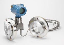
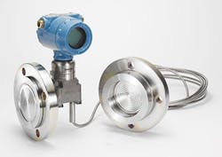
This type of remote diaphragm seal withstands the pressure and other attributes of the process fluid including its temperature and corrosiveness. The remote diaphragm seal moves in response to the system pressure and transfers that action to a fluid-filled capillary line that goes to the pressure transmitter. The remote diaphragm seal becomes the process containment point. Let’s examine how this works in greater detail.
Figure 1. Such a seal uses a large diaphragm to transfer pressure to a fill fluid and prevents problems caused by process fluid directly contacting the instrument.
A Versatile Approach
Diaphragms can serve as remote seals (Figure 1) in many pressure measurement applications that can accommodate their physical size. They can support gauge, absolute or differential pressure (DP), which extends potential use to flow and level measurements. Generally, a remote diaphragm seal is installed via a threaded or flanged connection, with available sizes ranging from ¼-in. NPT to 4-in. ASME flange.
The diaphragm surface area and stiffness determine the amount of pressure applied to the fill fluid, which must correspond to the process pressure so the instrument reacts correctly. Because it directly contacts the process, the remote diaphragm seal must be chemically compatible with the process fluid to avoid corrosion and other problems. If specialized alloys are necessary, only the remote seal assembly must be made of the costly material — unlike conventional impulse lines that require the material for their valves and fittings.
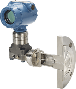
Figure 2. Process and ambient temperatures differing markedly may require use of a second fill fluid and, thus, an intermediate internal diaphragm.
The fill fluid also must suit the anticipated temperature range. This rarely is a problem because a wide selection of specialized oils are available; some resist boiling even at very high temperatures. Where the process temperature is high but the ambient temperature is low, a fill fluid that can withstand the high temperature may become too viscous to transmit pressure accurately if it must go far from the process heat. In such cases, inserting a second diaphragm between the remote seal and the transmitter allows use of a second fill fluid (Figure 2), more appropriate for the lower ambient temperature, for the leg attached to the transmitter. This expands the thermal range of the setup and avoids any need for heat tracing.
In many respects, a remote diaphragm seal’s greatest advantage is that it protects the instrument from the process. The remote seal bears the brunt of high pressures, high temperatures and corrosiveness. Others benefits include:
• Suspended solids and viscous fluids cannot clog impulse lines.
• Smooth and flush surfaces improve cleanability and other hygienic characteristics.
• Simpler impulse lines between the transmitter and remote seal reduce maintenance of wet and dry legs.
These benefits extend the capabilities of DP technologies for applications such as flow and level measurement.
Remote Diaphragm Seal Failures
After discussing all the advantages of remote diaphragm seals, we also must recognize that they can fail. Getting responsive and accurate readings requires thin diaphragms to transmit pressure. While the fill fluid provides even support, the diaphragms remain susceptible to corrosion; so, careful material selection is essential. Actual field failures, if analyzed appropriately, can provide important insights because the information gained can reflect on both the process and the equipment. Therefore, using the proper examination methods to analyze a failure is crucial for determining the true root cause.
The most common cause of failure involves an instrument being pushed beyond its design limits. This can occur for a variety of reasons. For example, the process fluid is more corrosive or erosive than expected. This can stem from a difference in chemistry, inclusion of abrasive solids, increases in fluid velocity and other factors. Consequently, the service life of the diaphragm declines.
These cases often reveal things about the process that operators didn’t realize or fully understand. However, in many cases determining the root cause depends on sophisticated testing methods. A vendor, through its analysis capabilities, often can help in pinpointing the culprit.
Most failures associated with remote diaphragm seals involve the diaphragm itself at the point of contact with the process fluid. Drawing on a wide collection of sophisticated tools is critical to determining failure mechanisms. Some are observational while others attempt to recreate circumstances of the failure. The most frequently used tools and methods include:
• Scanning electron microscope (SEM) — aids in determining material failure due to mechanical stress from corrosion or physical damage;
• Energy-dispersive x-ray spectroscopy (EDX) — ascertains via composition analysis if material failure stems from specific chemical exposure;
• Fourier-transform infrared spectroscopy (FTIR) — identifies presence of organic contamination and decomposition;
• Cross-section examination with high-powered microscopes — locates potential material fractures or porosity;
• X-ray fluorescence (XRF) — verifies plating materials and associated thickness;
• Positive material identification (PMI) — confirms material(s) of construction;
• Temperature effects testing — performs tests at specific temperatures or over a range of temperatures to reproduce field symptoms; and
• Performance accuracy testing — checks performance at zero, full scale or a specific pressure to duplicate field symptoms.
Now, let’s examine five actual cases to see how these methods can work together to identify problems and suggest solutions.
Case 1: Hydrogen Permeation
A chemical plant installed a Rosemount 2051T pressure instrument in combination with a Rosemount 1199 remote diaphragm seal made of Type-316 stainless steel in a process slurry application. After six months of service, the site reported that the instrument indicated a pressure exceeding 3 bar-g when no process pressure was applied. It also observed obvious bulging of the remote seal diaphragm although no leakage of fill fluid was seen.
Our lab verified both the false pressure indication and bulging. PMI showed that all the materials used in construction of the remote diaphragm seal assembly were correct. Failure analysis testing using gas chromatography indicated the presence of hydrogen gas in the fill fluid. It caused the increased pressure — but how did the hydrogen get there?
Single hydrogen atoms in the process fluid were able to diffuse through the stainless steel diaphragm. While this may sound impossible, Type-316 stainless steel is permeable at high temperatures; other specialized materials, such as Alloy C-276, are even more permeable. Once on the other side of the diaphragm, some of the hydrogen atoms combined into hydrogen molecules, which no longer could escape. Many factors, including high temperature, high pressure and galvanic corrosion, can accelerate the permeation rate.
The recommended solution was coating the diaphragm with gold plating or AbrasionShield (one of our SensorShield coatings) to reduce permeability.
Case 2: Fill Fluid Vaporization
Another chemical plant installed a Rosemount 3051S pressure instrument in combination with a Rosemount 1199 remote diaphragm seal in a polyurethane production unit. The fill fluid was Silicone 200. After seven months of service, operators noticed a pronounced reading drift when operating at a temperature of 365°F (185°C) and applied pressure below atmospheric.
When returned to our lab, the equipment appeared to be fully intact. However, discoloration of the instrument housing suggested extended periods of high temperature exposure. At atmospheric pressure, the assembly functioned as expected. Next, because the unit was used in a deep vacuum, a 0.44-psia (3-kPaa) vacuum was applied. Nothing odd happened initially until the assembly was tapped to provide a physical shock. Then, the reading immediately began to climb significantly. What could account for this reaction?
Operating at 365°F routinely in a vacuum situation using Silicone 200 fill fluid put the operation at the point where the vapor pressure curve for the fill fluid begins to climb steeply. Under these conditions, gas bubbles form in the fluid due to the high heat and vacuum pressure, distorting the reading. Eventually, some of the gas will re-dissolve but, like shaking a can of soda, a mechanical disturbance can cause the bubbles to re-form.
The recommended solution was changing to a fill fluid with higher temperature resistance to avoid potential for vaporization inside the capillary lines.
Case 3: Process Induced Mechanical Damage
A third chemical plant installed a Rosemount 3051L single remote diaphragm seal assembly with a Type-316 stainless steel diaphragm. After an unspecified period of operation with a 50% solution of sodium hydroxide, the diaphragm began to leak.
Examination with our SEM clearly showed the diaphragm had sustained heavy damage from particle abrasion, with sodium chloride deposits in multiple locations. EDX analysis also indicated chlorine attack but the process shouldn’t contain chlorine.
The process creates sodium hydroxide by electrolysis of sodium chloride, which also can result in unreacted chlorine. Chemical analysis suggested the diaphragm erosion was caused by unreacted sodium chloride crystals in the fluid combined with attack from the residual chlorine. Standard Type-316 stainless steel was inadequate for this application.
So, we recommended changing to a higher nickel alloy (e.g., Alloy C-276 or Duplex 2205) for the diaphragm to provide added strength or using an abrasion-resistant coating such as AbrasionShield.
Case 4: Invisible Corrosion
A chemical plant installed a Rosemount 3051C pressure instrument in combination with a Rosemount 1199 remote diaphragm seal with a Type-316 stainless steel diaphragm filled with Silicone 200 fluid. After about one month in hydrocarbon service operating at 400°F (204°C) and 130 psi (900 kPa), the facility reported a loss of fill fluid from the diaphragm face.
Visual inspection in our lab confirmed the leak. PMI verified the correct specified material for the diaphragm. SEM examination indicated a crack near the outside edge of the diaphragm within the heat-affected zone where the diaphragm was welded to the frame. Analysis by EDX determined that exposure to chlorine in the process had caused the crack.
We suggested changing to a higher nickel alloy (e.g., Alloy C-276) for the diaphragm because the site couldn’t rule out continued exposure to chlorine.
Case 5: Drifting Level Readings
Another chemical plant installed a Rosemount 3051C DP pressure instrument in combination with two Rosemount 1199 remote diaphragm seals for a level measurement application. The purchase order specified threaded seals with 0.006-in.-thick diaphragms and 16.4-ft (5-m) capillary lines on each side (high and low) in a balanced configuration. The setup was field calibrated and ranged for 0–50 in. (0–1,250 mm) H2O. During the first month of operation, it exhibited an unacceptable amount of drift.
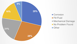
Figure 3. Corrosion and fill fluid problems, usually related to temperature, account for well over half the failures of remote seal systems.
The site returned the complete assembly to our lab for performance testing and, if necessary, failure analysis. In the lab, it performed within expected tolerances across the full measurement range at temperatures between -40°F and 185°F (-40°C to 85°C). No failure was detected.
The lab analysis concluded that no specific problem existed but the components didn’t suit the application. The requirement of 0.006-in.-thick diaphragms, twice the normal thickness, wasn’t necessary. The combination of these stiff diaphragms, the long capillary lines and the fluctuations in ambient temperature caused a high degree of fill fluid expansion, distorting the reading. Ultimately, the components were re-specified.
Understanding Problems And Solutions
Three causes account for more than three-quarters of remote seal failures (Figure 3), with process-induced corrosion just edging out fill fluid as the top culprit. As the cases just discussed indicate, sometimes finding the source of the problem isn’t easy. Corrosive chemical components turn up in situations where they may not be expected; so, in some cases, analysis yields critical information about the nature of the process that might not be discovered otherwise.
At the same time, incorrect specification of instrument components can result in short service life or poor performance.
To ensure you get a suitable system, take advantage of all the resources available from manufacturers during the product evaluation and specification stage. In the event of an actual failure, the vendor also can help you pinpoint the root cause and, thus, improve measurements and processes.
NATHAN STOKES is a director of product management for Emerson, Shakopee, Minn. PAT GOETTIG is a principal product quality engineer for Emerson, Shakopee, Minn. Email them at [email protected] and [email protected].


