How to Identify and Address a Water Hammer Event
In industrial applications, “water hammer” is a phenomenon that can have significant consequences beyond a loud hammering sound, which may be familiar to people in residential environments. For the chemical processing industry, water hammer can result in a disastrous pipe burst that can lead to costly downtime and potential losses.
Water hammer, also known as fluid hammer, or surge, refers to the pressure response due to a rapid change in fluid velocity in piping systems. When fluid is brought to a sudden halt, the momentum of the fluid is converted to potential energy in the form of pressure. The initial pressure spike due to an instantaneous halt in flow can be predicted by the Joukowsky equation. The Joukowsky equation has been used as a first approximation for more than a century to estimate water hammer pressure surges. Any rapid transient change can produce water hammer including events such as valve closures, pump startups and shutdowns.
Pressure surges following a water hammer event cause both high- and low-pressure waves, each of which may be uniquely problematic. High-pressure waves can exceed pressure ratings, induce large forces and cause excessive vibrations. Low-pressure waves can cause sub-atmospheric pressures, which can collapse equipment and form a vapor cavity if the pressure is reduced to the fluid’s vapor pressure. Subsequent vapor cavity collapse, when the pressure in the pipe rises, can cause secondary pressure surges. The propagation and reflection of the high-pressure wave will also result in a low-pressure wave and vice-versa. While the Joukowsky equation is a common hand calculation when considering surge, system pressures may exceed the initial Joukowsky pressure spike due to reflection and combining of pressure waves, vapor cavity collapse causing secondary pressure spikes, and line pack as pipe friction is recovered.
Although a single water hammer event may not be enough to burst a pipe or destroy a pump, repetitive stress over time due to water hammer can increase maintenance costs as weak spots in the system are worn down. The pressure response from water hammer events can be complex to predict, so computer simulation is recommended to account for the real effects of wave propagation and interaction in a particular system. Understanding the cause and effect of water hammer enables an engineer to mitigate its consequences.
How to Mitigate Water Hammer
Addressing water hammer during the design process provides an engineer more flexibility in mitigation strategies. For example, engineers could select non-slam valves before construction or adjust the system configuration to mitigate water hammer without purchasing additional equipment. Other cases may still call for equipment such as surge vessels, air valves, relief valves or similar devices depending on system requirements.
The options available to prevent or mitigate a water hammer event will depend on when the water hammer issue is caught and the cause of the water hammer event. There are two questions an engineer should focus on during the mitigation process:
- Can the transient event that creates water hammer be altered to prevent surge?
- Can the pressure surge wave be dissipated?
Do You Have a Transient Event?
A transient event refers to a component change that causes water hammer, such as a valve closing or pump tripping. Altering the event that initiates the water hammer transient can be effective if the event is slowed enough to no longer be considered instantaneous. A non-instantaneous event should prevent the full Joukowsky pressure spike, though the analysis is not always so clear-cut.
For the purposes of hydraulic analysis, a transient event is considered instantaneous if the event is shorter than the system’s communication time, or the time it takes for a pressure wave to travel to the farthest point in the system and back. The communication time can be calculated as two times the overall length of the system divided by the wave speed. If there are branching paths, then it is common to use the length of pipe from the component that is opening or closing to the end of the longest branching path. Keeping the communication time in mind is important as even relatively slow transients may still act as instantaneous closures given the right circumstances. Here’s a look at scenarios in which valves and pumps can cause a water hammer event:
Valves
The most considered source of water hammer is valve closures. For this discussion, we’re talking about any type of valve, including manually operated valves, check valves, control valves, relief valves, air valves, etc.
Operators should consider the inherent and installed characteristics of a valve to understand the full impact of a closure. “Inherent characteristics” are mainly driven by valve geometry and measured by the manufacturer. This could include the valve’s characteristic curve (Cv vs. open percentage) and full open-pressure loss. “Installed characteristics” are how the valve behaves when installed in the actual system and can be thought of as the pressure drop ratio of the valve to the system. Installed characteristics can be influenced by all components in the system, including the system’s length, pipe friction, pump curves and other fittings and losses. The more pressure loss through the valve, the more likely it is to control the flow rate through the system to gradually slow the fluid.
Both the inherent and installed characteristics of the valve will determine the pressure response at the valve.
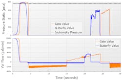
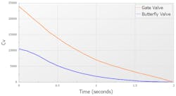
Consider the below graph comparing pressure and flow for a relatively short system in Figure 1. The orange and blue curves compare the response for an 18-in. gate valve to an 18-in. butterfly valve in the same system. The Cv vs. time graph also can be seen below in Figure 2, reflecting each valve’s characteristic curve.
For this example, assume the fastest closure time for both valves is 2 seconds, which is shorter than the communication time of 3 seconds. This indicates that the 2-second valve closures would be considered instantaneous and should see the full Joukowsky pressure rise. At 2 seconds, the gate valve pressure rise is exactly the Joukowsky pressure rise of 744 psi, but the butterfly valve experiences a slightly larger pressure rise. The extra pressure at the butterfly valve comes from line pack, as frictional pressure is recovered at the valve as flow begins to halt sooner than with the gate valve. After 2 seconds, the pressure at both valves continues to increase due to line pack. Ultimately, the gate valve experiences the higher maximum pressure as all the line pack pressure accumulates at once, unlike with the butterfly valve where some pressure is dispersed before the maximum pressure is reached.
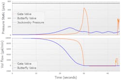
Now, consider the case where both valves close over 30 seconds, which is much longer than this system’s 3-second communication time. For this case, both valve closures are not instantaneous, and neither valve sees the full predicted Joukowsky pressure rise as seen in Figure 3.
In this case, the gate valve still causes a larger pressure spike due to the much steeper flow rate decrease at the end of the valve closure, showing a dependence on the valve’s characteristics as to when each valve starts reducing flow.
As shown through the above example, a few key strategies exist to reduce surge pressures. In all cases, consider ways to reduce the velocity change and pressure surge. This may involve changing the system to reduce the operating velocity in the lines, such as choosing a larger pipe size or introducing equipment.
For valve closures, if possible, reduce the closure rate at the end of the valve closing time to gradually decelerate the fluid. This can involve lengthening the valve closure time, using an 80/20 valve closure (closing the valve 80% in the first 20% of the closure time), or choosing a different type of valve with a gradual Cv change at lower open percent values. Look for valves with characteristic curves that close quickly early in the closure, then slow down later. For cases where surge originates at valves like check valves and relief valves, look for valves marketed as “No-Slam” as these options will typically be engineered with the above options in mind.
Pumps
The other common source of pressure surges in systems is pumps. As pumps start up or shut down, the energy imparted by the pump to the system can rapidly change fluid velocity, resulting in water hammer events. For routine operations, using a variable frequency drive (VFD) at the pump to control the pump speed ramp is the simplest and most efficient solution to prevent surge. However, emergency cases where the pump trips, nullifying the VFD, must also be considered.
Predicting how fast a pump starts or trips largely depends on the rotating inertia of the pump. Calculations for the pump transient can be very dependent on the total rotating inertia, so performing a sensitivity study using one-half times the predicted inertia and two times the predicted inertia is recommended by engineering sources, such as “Fluid Transients in Pipeline Systems” by Thorley.
Mitigating unacceptably high pressures due to a pump transient often is more complex than addressing other events due to the more complex nature of the pump. One measure to consider is installing a flywheel on the pump shaft to increase the rotating inertia of the pump, forcing a slower pump trip.
Besides using a flywheel or VFD, changing the system configuration to reduce the fluid acceleration is another means to decrease the pressure surge in the system. This may involve adding a recirculation loop, or other means to redirect flow at the pump. Reducing the fluid acceleration may also be accomplished using components such as surge vessels, which are discussed further in the next section.
Can You Dissipate the Pressure Surge?
In some situations, such as for existing systems, the component changes discussed above may not be available Alternatively, the piping layout may cause operational changes to be ineffective for surge mitigation. In these cases, other safety measures may be required to alleviate the surge wave.
For high-pressure surges with unacceptable pressures, consider options such as closed surge vessels or relief valves depending on the application. To address low-pressure concerns, consider surge vessels or air valves to avoid sub-atmospheric pressures. Here’s a look at the different options and how they might help during a pressure surge:
Surge Vessels. This term can refer to a closed tank or an open tank that supplies or absorbs flow during a transient. Both types of vessels can combat a high- and low-pressure surge by absorbing fluid to reduce the pressure during high-pressure events and supplying flow into the pipes during low-pressure events to keep the pipes pressurized. One advantage of surge vessels is they can keep the operating fluid contained and prevent air from entering the system. The disadvantages are that surge vessels can require a large amount of space and may require frequent maintenance to maintain pressure in the vessel.
During sizing, place surge vessels as near to the source of the transient as possible. However, keep in mind that a poorly located surge vessel can potentially make surge waves worse due to acoustic resonance or check-valve slam, so location is crucial. The size of the vessel will depend on the magnitude of the wave that is being absorbed by the vessel, with a larger tank being required for larger flow rates/pressures.
It is recommended to work with the surge vessel vendor when selecting a vessel for the system as the sizing process is complex and mistakes can be costly.
Relief Valves. Designed to open at a specified pressure, relief valves quickly reduce the pressure in the system and protect sensitive components from high pressures. These valves are relatively low maintenance but can cause the loss of working fluid depending on the configuration. They can be installed to open to atmosphere or into a contained tank depending on the fluid.
Standards such as API 520/526 provide information on best practices for sizing relief valves. It is important to consider all operating cases when choosing a relief valve. Poorly sized relief valves can cause operating issues if they close too quickly or if they repetitively open and close, known as valve chattering.
Air Vacuum Valves. To prevent vacuum conditions, air vacuum valves let air into the pipe when the pipe’s pressure reaches atmospheric pressure. As the pressure rises in the pipe, the air is then driven out of the pipe causing the valve to close. Air valves also can open to release pockets of air in the pipes. Air valves can’t be used with fluids that are flammable or reactive with air, so they are often only used with water systems.
Air valves are often sized to match the pipe size in inches, so a 1-in, air valve would be suitable for a 1-ft diameter pipe. Typically, air valves should be located at high points in the line or near sources of low pressure. Perform simulations to confirm the sizing and location of the air valve; if the valve is too small vacuum may not be prevented, but too large and air pockets may be trapped in the pipeline, causing further water hammer events.
By assessing potential water hammer events during the design process, chemical processing plants can prevent surge waves and serious damage to their system. For existing designs, plants can install mitigation equipment, such as surge vessels, relief valves, and air vacuum valves, when simpler changes are not possible.