Cut the Cost of Waste Gas Incineration

The module is an insulated box full of heat exchange media, usually ceramic packing. At least two modules are used — one absorbs heat from the flue gas while the other sheds heat into the waste gas (Figure 1). When a box has absorbed all the heat it can, it’s taken offline; waste gas then passes through it backwards until the box is cool again. Once cooled, it’s returned to handling hot flue gas. Two boxes are needed so the flue gas always has a path to the exhaust stack — specialized valves set on a timer switch each box from heating to cooling every 5 minutes or so.
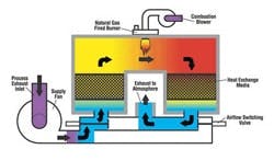
Figure 1 -- Two-bed RTO:
Heat exchange media alternate
between heating and cooling.
Diagram courtesy of CMM Group.
In this way, if one pound of waste gas enters at 70°F, one pound of flue gas exits at 200°F. With other thermal oxidizer designs, the pound of flue gas may exit at 500°F or 1,600°F — a lot more heat is lost up the stack. If the waste gas is lean, most of this heat comes from firing auxiliary fuel. The popularity of RTO units stems from the desire to cut such fuel costs.
The Basics
Waste gas incinerators react oxygen with waste hydrocarbons at high temperature to produce a clean flue gas. A perfect incinerator would have a destruction and removal efficiency (DRE) of 100%, zero fuel usage and zero emission of carbon monoxide and nitrogen oxides. A small amount of the original hydrocarbons always remains, though. If 1% is left, the DRE is 99%. Some CO and NOx always are produced, too. However, NOx emissions are lower for an RTO than for almost any other type of thermal oxidizer. Table 1 compares various options.
Thermal Oxidizers
Type |
Waste Types |
Heat
|
Stack
|
Maximum
|
Heat recovery method |
| Direct fired | Any gas or liquid | No | 1,200–2,200 | 98–99.99+ | None |
| Catalytic | Lean waste gases | Yes | ≈500 | 95–99+ | Metal gas/gas heat exchanger |
| Recuperative | Lean waste gases | Yes | ≈500 | 95–99.9+ | Metal gas/gas heat exchanger |
| Boiler | Any gas or liquid | Yes | 350+ | 98–99.99+ | Boiler and economizer |
| RTO | Lean waste gases | Yes | 200–300 | 95–99+ | Packed beds |
The U.S. Environmental Protection Agency and local air boards require DRE values from 95% upward, and CO and NOx emissions measured in the “tons per year” range. Fuel usage is up to the operator but more fuel means higher operating cost and more greenhouse gases, so lower is better.
For good DRE values, furnace temperature must be high enough, residence time of the flue gas in the furnace must be long enough and 2% to 3% O2 must remain in the flue gas leaving the stack. Stack temperature doesn’t matter — furnace temperature is all that’s important.
For most incinerators, furnace temperature is 1,400°F to 1,600°F. Higher temperatures require more expensive refractory to avoid heat damage. Furnace residence time typically is 0.5–1 seconds. Hydrocarbons that are hard to burn, like pesticides, may require more time. Oxygen content usually is about 3% or more by volume; as low as 2% O2 might be OK. If the waste gas is “dirty air,” it will contain all the oxygen needed. Otherwise outside air has to be added.
If the waste gas is relatively rich with hydrocarbons, a simple “direct fired” thermal oxidizer with a small burner will do the job. In this case, heat recovery is unnecessary but you can add a boiler if you need steam for process heating or to generate electricity.
Lean waste gas, in this situation, may require a large burner. That means some sort of heat recovery will make sense, because the cooler your stack gas, the lower your net operating costs. An RTO recovers heat very efficiently.
Limitations
While an RTO is the most fuel-efficient oxidizer, it doesn’t suit all applications:
• A waste gas with entrained particles or droplets may cause fouling of the heat exchange media. In-place cleaning of the media is difficult or impossible. Fouled media means pressure-drop and efficiency problems. A direct fired oxidizer would be better.
• An intermittent waste gas requires idling or shutting down the RTO when waste isn’t flowing. It can take several hours to heat an RTO system for operation. A direct fired oxidizer probably would be better.
• Too rich a waste gas may lead the RTO to be too efficient, resulting in furnace temperatures that can cause refractory damage. If the waste-gas heating value significantly exceeds 20 Btu/ft, an RTO is a bad choice. Most RTO designers want waste gas no richer than 25% of the lower explosive limit.
• A waste gas containing chlorinated hydrocarbons, like methyl chloride, or sulfur bearing compounds, like hydrogen sulfide, will form a stack gas that might produce acid droplets if cooled enough — keep in mind that an RTO provides cooler stack gas than other types of oxidizer. If acid droplets are expected, you may need special construction, driving up cost.
Avoid Common RTO Mistakes (near the end of the article) summarizes some common mistakes in RTO selection and operation.
The Role of Packing
Directing the lean waste gas through a packed bed enables its temperature to be brought close to the target furnace temperature using only residual heat left in the bed by the hot flue gas. Sometimes this results in the waste gas hydrocarbons igniting on their own, achieving a further rise in temperature. While an RTO furnace always has a fuel gas burner, with good design fuel gas consumption might be zero during normal operation.
Without heat exchange packing, an operating RTO would perform like an ordinary incinerator — fuel usage to reach the needed furnace temperature would be high with a lean waste gas. More bed packing lowers fuel gas needed or raises furnace temperature reached.
If the beds were never switched, an RTO would perform like an ordinary incinerator — the hot flue gas would heat the bed it’s flowing through to the flue gas temperature and the lean waste gas would draw all of the heat out of the other bed. Fuel consumption would be high with a lean waste gas. Shorter bed switching time reduces fuel gas needed or increases furnace temperature reached.
The flow and composition of the waste gas determine bed size and packing type. You must use enough packing to absorb the heat from the full flow of stack gas — once a layer of packing is heated to combustion chamber temperature, it can’t pick up any more energy so another layer must be added. The designer sets the pounds of packing in each bed according to the rate of stack gas flow and the time the bed is absorbing heat before it’s switched. The type of packing used is an economic decision — random packing is cheaper but structured packing (Figure 2) takes up less room for the same amount of heat transfer.
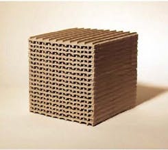
Figure 2 -- Typical ceramic block:
Structured packing requires smaller
volume than random packing for the
same heat transfer.
Photo courtesy of Lantec.
Bed construction and the flow and composition of the waste gas dictate bed switching time. For greater heat-transfer efficiency, switching time needs to be shorter. But with larger beds switching time can be extended because there’s more packing to absorb the heat. Every time the beds switch, a small burst of unburned waste gas flows to the stack; a high required DRE mandates longer switching times, which results in larger packed beds.
Varying Quality Gas
A waste gas that usually is lean but occasionally can be richer demands special attention, as waste gas with more hydrocarbons requires less heat recovery to maintain low fuel-gas consumption. To reduce the heat recovery efficiency of the system, you can remove bed packing — but this is difficult. So, in such situations, units generally rely on either cold gas bypass (CGB) or hot gas bypass (HGB) to divert some gas around the heat recovery section of the RTO. With CGB, part of the cold waste gas is ducted directly to the furnace; with HGB, part of the hot furnace exhaust is ducted directly to the stack.
CGB and HGB also are used to keep the furnace from reaching an excessive temperature, which could cause permanent refractory damage or require specification of a different refractory grade. A typical high-temperature-shutdown set point might be 1,800°F.
HGB gives a higher stack temperature than that for most RTO designs. Special stack construction (stainless or refractory-lined carbon steel) may be required to avoid damage.
During normal operation RTO furnace and stack temperatures vary over a narrow range. This is because when the beds switch the waste gas entering the furnace (and the furnace gas entering the stack), they now are flowing through the alternate bed. The waste gas suddenly is hotter because it’s flowing through the bed recently in contact with the hot flue gas. The flue gas suddenly is colder because it’s flowing through the bed recently cooled by the incoming waste gas. If the beds switch every 5 minutes, the flue gas and combustion chamber reach their “average” temperatures approximately 2.5 minutes after the switch.
Different dynamics In a direct fired incinerator increasing the fuel flow results in hotter stack gas within 5 seconds to 10 seconds. In an RTO increasing the fuel flow to the burner immediately heats the furnace — but the stack gas temperature rise is delayed by the heat absorbed in the packed beds. The higher RTO furnace temperature puts more heat in the packed bed receiving the flue gas. At the end of the cycle that bed is hotter than at the end of the previous cycle; when the waste gas is switched back into it the waste gas temperature entering the furnace will be higher than in the previous cycle. The stack temperature as well as the furnace temperature will swing around an average value as the bed switching proceeds. In fact, a step change in fuel flow may require several cycles of bed switching to reach stable average stack and furnace temperatures.
This type of delayed response happens with any variation in RTO operation, including changes to waste gas flow, waste gas hydrocarbon content, burner fuel or air flow, and CGB or HGB flow.
Design Considerations
As we all know, every pound of waste gas, air or fuel gas entering must be matched by a pound of flue gas out the stack and every Btu entering the RTO (as sensible heat due to a heated waste gas or as hydrocarbon heat release) must show up as a Btu in the stack gas or as heat loss through the vessel shell. What happens in the packed beds or the switching valves is important for saving fuel but, taken as a whole, “what goes in has to equal what comes out.” So, for instance:
• If it’s impossible to feed enough air to produce around 3% oxygen in the stack gas, then the RTO can’t operate as intended.
• If the measured stack temperature is higher or lower than predicted by the Btu balance, then some other input isn’t being considered — maybe the waste gas is richer or leaner than expected.
Given a specific waste gas, air flow, fuel gas flow and heat loss through the vessel refractory and insulation, you can calculate the stack gas flow, composition and temperature even if nothing is known about the bed packing, switching times, bypass flow or any other detail.
RTO design involves eight steps:
1. Perform a heat and material balance on the waste stream, including minimum/maximum flow, minimum/maximum hydrocarbon load, etc. Determine if any of the cases excludes use of an RTO — for instance, is the waste-gas hydrocarbon load so high that a different type of incinerator would make more sense?
2. Specify the packing types and amounts, along with the bed switching times to achieve the heat recovery efficiency needed for all operating cases. Packing vendors can provide these calculations for their products.
3. Size the combustion chamber, stack, inlet ducting, any bypass ducting, etc.
4. Size and specify the waste gas blower, fuel gas burner and combustion air blower.
5. Specify the type and amounts of refractory lining and external insulation.
6. Prepare the process and instrumentation diagram and process flow diagram(s).
7. Put together specification sheets for purchase of blowers, burners, instruments, etc.
8. Prepare fabrication drawings, parts lists, operating instructions and other documentation.
An Attractive Alternative
An RTO provides the highest fuel efficiency of any type of waste-gas thermal oxidizer and, thus, may allow you to cut costs for incineration. However, it isn’t best for all services, so you must understand its limitations. When an RTO is the right choice, you must then consider its particular design and operational issues.
Avoid Common RTO Mistakes
Most RTO problems stem from incorrect application of the technology:
• Waste-gas heating value is higher than expected. The RTO overheats without major changes to the system (e.g., removing packing or installing hot or cold bypass). This may cause premature ignition of waste or even flashbacks to the process.
• Waste-gas heating value is lower than expected. RTO fuel usage will be high. The fix requires addition of heat exchange packing, which may be limited by chamber dimensions.
• Waste gas has unexpected particulate matter. Simple dusts will block gas passage through the heat exchange medium but can be vacuumed off. Reactive particles can bond to the medium, ruining it and, thus, requiring bed replacement. Combustible particles may collect in the medium and light off, causing thermal damage. Waste gas filters might be needed.
• Waste gas flow is greater than expected. Pressure drops through the RTO system may require larger blowers or different heat exchange medium.
• Waste gas flow is intermittent, with rapid startups required. From a standing start an RTO system can require several hours of heat-up. Abrupt flow or heating value changes cause temperature excursions and higher stack emissions.
Other RTO problems involve operating and maintenance practices:
• Nuisance shutdowns tempt operations to use automatic restart logic. Stay with manual restarts to catch potential safety problems and avoid disaster.
• Maintenance takes shortcuts. Using the wrong type of replacement thermocouple, leaving access doors loose (leaky) and other casual mistakes can result in elevated emissions, thermal damage or worse.
• Staff doesn’t pay due care with the waste-gas gathering system. Spilling solvent under a process vent collection hood can convert the low-Btu waste gas into a high Btu hazard for the RTO.
• Seasonal plant operating changes are ignored. Fuel usage can creep up. So, review RTO bed switching times. They affect heat recovery and fuel usage.
• The refractory lining is neglected. It doesn’t last forever. Look for developing hot spots so you can schedule repairs to avoid unplanned shutdowns.
Dan Banks is principal consultant for Banks Engineering, Inc., Tulsa, Okla. You can e-mail him at[email protected].