Module Type Package (MTP) Accelerates Automation Integration

Automation usually is on the critical path of any major project. As a result, delays to integration often directly contribute to delays in completion and startup.
Most automation integration takes place in the late stages of a project because the relevant information is not available until that time. Sometimes known as a “last in, first out” situation, much of the work related to automation must wait until earlier stages are finished; so, any prior schedule slippage has a compounding effect.
Automation integration has many aspects but this article will concentrate on one specific area: incorporating intelligent devices (IDs). We’ll define these as any piece of equipment with its own internal control system, such as a programmable logic controller (PLC) or similar device. IDs range from a relatively simple mixing system to a complete gas turbine/compressor train, and any type of automated equipment in between. At chemical plants, the key issue for IDs is integrating their local controllers with the distributed control system (DCS) or other automation host running the overall process unit.
Integration typically involves multiple functions:
• communicating process and supervisory data from the ID to the DCS;
• sending commands (e.g., for start/stop, changing setpoints, etc.) from the DCS to the IDs; and
• uploading diagnostic data from the ID to the DCS.
Bidirectional communication is necessary to carry out these functions; depending on the complexity of the ID, the amount of information exchanged can be enormous. The ability to collect data has grown in recent years, so system designers often increase the volume because they can. A gas turbine/compressor train easily could have 1,000–2,000 tags. Every tag obviously does not need to be addressed but technicians must consider them all during the design and select which are required.
The Problem Of Complexity And Scale
This situation is complex enough on its face but made worse by the scale. A chemical processing unit can have dozens of IDs. Projects frequently include many medium- to large-scale units (e.g., skidded equipment, utility systems, chemical injectors, filters, etc.).
To minimize “stick building” on the site of a new plant or process unit, operating companies generally favor having equipment fabricated and assembled elsewhere whenever practical. This results in more equipment coming to the site on skids or some other modular form, outfitted with a PLC to do the local control work.
Ideally, integrating an ID with the DCS should be a methodical process following a series of defined steps. Unfortunately, in the real world, few projects can be so systematic due to time pressures or a variety of other reasons.
The vendor or original equipment manufacturer (OEM) creating the ID as a package likely subcontracts some of the systems integration (SI) work. The person(s) writing the actual program code for the PLC controlling the skid — and the associated human-machine interface (HMI) — could be a subcontractor of a subcontractor, several levels removed from the end-user company.
So, an engineer trying to get the DCS to talk to the ID can’t count on readily accessible help from the person who put the program together originally. Moreover, the OEM providing the skid may have taken steps to guard the SI program from the installer or end user in an effort to protect its intellectual property.
To make matters worse, a project may involve dozens of skids from many different vendors. The solution to a problem on one may not transfer to others; so each skid provides a whole new set of challenges. Smaller-scale IDs are more likely to be standard off-the-shelf designs and, so, may allow a higher degree of copy-and-paste programming across multiple units.
How Integration Works Now
At present, the actual integration method shows little consistency because there are so many variables:
• manufacturer and type of the ID’s controller;
• complexity of the ID’s function(s);
• degree of the ID’s uniqueness (semi-standard to fully customized); and
• DCS to ID communication options.
In most situations, the final DCS integrator must perform many steps much later in the project than desired, often on a compressed timeline. This work can occur as late as during the site-acceptance-test phase when the skid is going through final installation. In addition, the integration sometimes becomes an iterative effort as skid programs are updated during troubleshooting or new functionality is identified.
Hopefully, documentation for an equipment package will include a clear mapping of all the tags that enables identifying which are necessary for process control, operator HMIs, diagnostics, historizing and alarms. The DCS then would access these points over a variety of serial and Ethernet protocols such as Modbus, Ethernet/IP, PROFINET, OPC UA, etc. For each point, it is important to define a description, engineering units, scaling ranges, read/write/read-write capability, alarm values/messages and more.
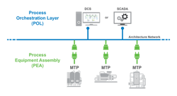
Figure 1. Intelligent devices (skids and other subsystems) are on the PEA layer and communicate via a common architecture network with the distributed control system (DCS) on the POL layer.
Often, the definition is transferred as a spreadsheet with hundreds or even thousands of lines. Such a spreadsheet not only is difficult and time-consuming to create and maintain but also is subject to human error in data entry. And, if the project is running behind schedule, the integrator must sort through it and do the analysis as quickly as possible.
Because these tags are transmitted over a communication link instead of a hardwired connection, they often are called “soft I/O [input/out].” Therefore, once the map has been sifted and straightened, the integrator configures the DCS so it can access the soft I/O from each ID using the appropriate protocol, connecting these points to DCS tags with all the proper characteristics. During commissioning, all soft I/O require loop checking much like hard I/O.
DCS-to-PLC communication is relatively slow compared to operation of native hard I/O points, so the soft I/O approach is reserved primarily for monitoring and supervisory functions. The finalized code and resulting communication must be tested and corrected during commissioning. If the skid gets replaced with a different configuration or the PLC changes, the code likely is useless.
Clearly, this is a slow, expensive and, often, error-prone process.
Easier Integration Of Modular Systems
Project teams need a more-standardized method to avoid having to create so much specialized integration so late in the process. Fortunately, there now is a far-more-hospitable environment where the integrator can connect the DCS with IDs over a common architecture network. This more-standardized method also enables integration with IDs, such as on-line asset monitoring systems, historically not linked to a DCS.
This environment is described in NAMUR NE 148, “Automation Requirements Relating to Modularization of Process Plants.” It lays out the concepts and specifications of Module Type Package (MTP), a vendor-neutral description language designed to simplify data integration. Specifically, MTP serves to populate the data characteristics of IDs with the DCS. It concentrates on five common interface categories when integrating all manner of complex equipment into the larger DCS, including:
• process control;
• safety and security;
• alarm management;
• HMI; and
• maintenance diagnostics.
MTP is not a communication protocol in itself but facilitates communication by presenting the decentralized intelligence contained within the IDs in a more-consistent way that is easier to format and transfer. NE 148 defines two layers (Figure 1). The first is the Process Equipment Assembly (PEA) Layer where the IDs and other subsystems live. Using MTP, they become the modules: they present their process data, diagnostics and even HMI graphics using a library of standard data objects. The assembly of objects representing the individual ID is exported from the PEA and then imported by the second layer, the Process Orchestration Layer (POL), which contains the DCS, such as Emerson’s DeltaV, or other higher-level process automation host system. It provides operations, supervisory control and visualization for the operators.
During configuration, the MTP definition is exported from each PEA ID and then imported into the POL DCS. Once the DCS begins production operation, the active communication mechanism with each ID is via OPC UA over standard Ethernet, which provides safety and security support. This import/export activity eliminates the need for the integrator to sift through all the mapping and write specialized code to connect with soft I/O.
This results in a shorter, cheaper and less-complex process than manual methods. The controller associated with a given ID must have the software necessary to allow it to function as a PEA layer device. This is where NE 148 comes in. It provides a library of data objects that can be customized and applied to various PLCs and other ID controllers to create the MTPs.
Uniformity With Flexibility
Given the wide range of potential IDs to be integrated, NAMUR NE 148 has created a more-adaptable structure as a recommendation rather than a standard. NAMUR will not review and certify products or MTP implementations under NE 148. The instructions and object libraries are in the recommendation; however, there is room for some interpretation. This means the MTP created by one PLC manufacturer will not necessarily be identical to that from another vendor for an equivalent ID.
So, a given situation with a specific ID and DCS will call for some tweaking, particularly if they come from different vendors. However, while implementations across a mix of vendors will not always be completely automatic, they are greatly simplified.
A vendor that offers both PLCs and DCSs has the opportunity to optimize the MTP definitions for its products so they match perfectly from layer to layer. For instance, if a plant is using an Emerson DeltaV DCS to run a process unit and adds an ID skid controlled by an Emerson PACSystems PLC, the connection from PEA to POL will be seamless right out of the box. Naturally, all this operates within the bounds of NE 148 but any interpretations will be made the same way, ensuring the easiest, fastest and most-robust implementation.
Where Is MTP Now?
MTP is new and parts of the standard still are being finalized. Organizations are learning and evaluating where they can apply it in existing plants or greenfield projects.
Because MTP was conceived and crafted by users and vendors in the chemical industry, organizations in that industry that were heavily involved with its creation are starting to embrace MTP and evaluating its implementation to realize project cost savings. While only a few project teams have implemented MTP so far, adoption likely will accelerate as more vendors release compatible products and organizations see the benefits and low risk of implementation. MTP’s potential savings are generating a great deal of interest and positive commentary.
Vendors also are ramping up efforts in anticipation of significant demand. These companies are training internal personnel so they can help customers understand MTP’s benefits and how it unlocks significant savings and reduces timelines in new projects. Emerson, for example, already has substantial experience implementing OPC UA protocol on projects and simply is adding another layer of understanding with MTP integration.
The Road Ahead For MTP
NE 148 Parts 1–3 are finished, making the whole standard complete enough for field use today and for organizations to benefit. However, automation vendors have some catching up to do. To be suitable, any PLC or other controller must have Ethernet connectivity and support OPC UA at a minimum and will need the basic supporting software. The way in which MTP will be added to a DCS platform depends on the vendor and likely would require a user to upgrade to a current version. How MTP unfolds in the larger automation market will depend on how enthusiastically system integrators and end users call for its availability.
The value of NE 148 is clear to integrators and end users. They know that existing manual methods consume many hours, resulting in increased costs, greater risk and creation of maintenance headaches over the long term. Operating companies suffer from slower time-to-market for new products and even quality issues with output. Because manual integration uses custom-written code, it also has a high potential to create security vulnerabilities that a hacker might exploit.
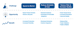
Figure 2. NAMUR NE 148 helps reduce cost and integration time and delivers other benefits.
NE 148 and its MTP methods provide a way to address all these concerns (Figure 2). By enabling equipment to be modularized, production flexibility increases. By standardizing interfaces, the traditional pains of integrating equipment go away. The result is shortened integration schedules, fewer errors, better quality and, ultimately, lower total cost of ownership for major production assets.
Using MTP, ID vendors produce a standard export file that is easy to import into any compliant DCS platform. This eliminates guesswork, even when there are numerous ID vendors. OPC UA becomes the real-time communication protocol for interfacing each ID to the DCS with the desired level of interoperability and security. MTP eliminates complex prototyping requirements during project execution while shortening integration, testing, startup and commissioning steps. New construction and upgrade projects ultimately achieve a shorter overall schedule and lower costs during a highly critical phase.
JUAN CARLOS BRAVO is product manager for PK controller and data integration for DeltaV at Emerson, Round Rock, Texas. Email him at [email protected].