Continuous Level Monitoring Bolsters Safety
Failure to identify and prevent spills and leaks from large hydrocarbon storage tanks at refineries and terminals can have catastrophic consequences — as the massive explosion and fire in 2005 at the Buncefield oil storage terminal in the U.K. exemplifies. It resulted in more than 40 people suffering injuries as well as extensive property damage. (For details, see: “Buncefield: Why did it happen?”)
Therefore, it is essential for organizations to implement robust safety measures that minimize risk and comply with the two key global standards relating to overfill prevention. The International Electrotechnical Commission’s IEC 61511 standard “Functional safety — Safety instrumented systems for the process industry sector” provides best safety practices for the implementation of a modern overfill prevention system (OPS) in the process industry. The American Petroleum Institute’s API 2350 standard “Overfill Protection for Storage Tanks in Petroleum Facilities” details best safety practices in the specific application of non-pressurized above-ground large petroleum storage tanks.
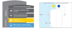
Figure 1. Properly addressing the risk of spills and leaks requires employing a series of independent protection layers (IPLs).
These standards recognize that minimizing the risk of spills and leaks requires employing independent protection layers (IPLs), as depicted in Figure 1. The basic process control system (BPCS), which monitors and regulates the production processes to ensure they are running smoothly, forms the primary layer of protection. If the BPCS is functioning correctly, the other layers will not need to become active. The second layer of protection is the OPS, which must remain separate and independent of the BPCS to provide redundancy. The OPS should stop an overfill from occurring if the BPCS suffers a failure or problem.
The third layer of protection is a secondary containment area, to minimize the consequences should an overfill cause spillage or tank damage result in a leak. When storage tanks are being filled and emptied daily, leaks often can go undetected given the huge volumes of product. However, even a small leak, over time, can lead to a substantial accumulation of hydrocarbons in the containment area; because this accumulation usually is spread over a large area, it can go unnoticed during visual inspection rounds. In the case of hydrocarbon storage tanks, the containment area typically is an underground pit or dike surrounding the tank into which liquid goes to prevent further spreading. In the unlikely event that all these layers fail to prevent or contain an overfill, there is an emergency response layer, which involves alerting the fire department or other appropriate service.
Monitoring Methods And Requirements
Historically, the monitoring of containments areas has involved visual inspection by personnel during manual rounds of the site. However, this method is time-consuming, places workers in hazardous areas, and can result in spills or leaks going unnoticed for some time — which then can delay essential repairs and clean-up activities and risks a vapor cloud spreading across the facility and igniting, as happened at Buncefield.
While the IEC 61511 and API 2350 standards cover overfill prevention measures inside tanks, many countries and local authorities have their own codes of practice relating to the containment area outside the tank. The conditions outlined within these codes of practice can vary but typically include requirements relating to the volume of liquid the containment areas must hold as well as the construction materials for them. However, no regulatory requirement forces companies to install level measurement instrumentation to detect spills and leaks through continuous monitoring of containment areas. Nevertheless, some organizations recognize the valuable safety benefits this additional layer of protection (Figure 2) provides and require automated monitoring of containment areas at their sites.
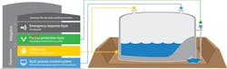
Figure 2. Automated monitoring of secondary containment areas makes this layer of protection active rather than passive.
Technology Selection
This was very much the case for a global oil and gas company that wanted to install continuous level monitoring in the secondary containment areas around hydrocarbon storage tanks at its facility in Antwerp, Belgium, to fortify its protection against the potential consequences of leaks. The firm sought instrumentation that could detect leaks as quickly and reliably as possible, to increase site and personnel safety. This ruled out basic point-level-detection devices such as vibrating fork switches because secondary containment areas are open to the elements. So, rainwater as well as hydrocarbons can accumulate there; point level detectors cannot distinguish between the two liquids.
Initially, the company installed hydrocarbon detecting sensors. However, these probes were not sufficiently robust; short circuits regularly caused false fire alarms.
Thus, the firm sought alternatives from several leading automation technology vendors. Its requirements included the capability to cover the full containment area, to measure an interface between oil and water, and to detect hydrocarbons from a thickness of 60 mm. The technology also would have to be unaffected by weather changes in the containment area and be able to operate reliably whether the area was dry, contained one liquid (water or hydrocarbon), or two liquids (water and hydrocarbon, requiring both level and interface measurements). The company also wanted wireless signal capability, due to the limitations of its existing cabling infrastructure, along with the possibility of adding further measurement points in the future.
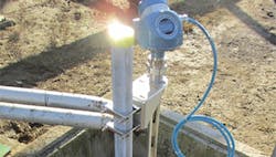
After considering the various proposals, the company selected Emerson’s Rosemount 5300 Level Transmitter, which uses guided wave radar (GWR) technology. In September 2019, it purchased 44 units for use on all secondary containment areas at the Antwerp facility (Figure 3). The installation also included a new WirelessHART network, with each area equipped with an Emerson Wireless 1410D gateway with 781 Field Link antenna, enabling the signal from the measurement points to go directly into the distributed control system (DCS).
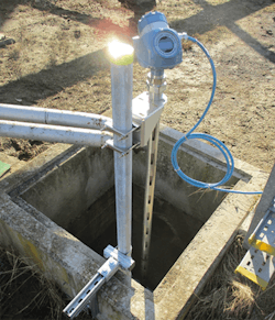
Figure 3. Site is using 44 of these transmitters for automated monitoring of secondary containment areas to provide greater visibility of potential leaks.
The Benefits Of GWR
In GWR technology, low energy microwave pulses are guided down a submerged probe. Microwaves reflected back to the transmitter from the surface enable level measurement. Because a proportion of the emitted pulse continues down the probe, the technology also can detect an interface, which makes it ideal for identifying the presence of oil as well as water in containment areas. In addition, GWR transmitters are very easy to install and do not require compensation for changes in the density or conductivity of the liquid. The technology is practically unaffected by buildup, eliminating the need for recalibration. As there are no moving parts, maintenance requirements are very low, reducing operating costs, while advanced diagnostics ensure quick alerting of operators to any degradation in performance. Although not used in this specific application because of the existing cable infrastructure, the availability of wireless GWR transmitters can help minimize the costs of installation by removing the need for data or power cabling.
GWR transmitters are proven and widely used in interface level- measurement applications. However, the upper liquid layer typically must be between 50 mm and 200 mm, depending on the liquid properties and antenna selection, to enable the device to distinguish between the signals reflected from the two different liquids. With containment areas being very large, that can mean a considerable amount of hydrocarbon leakage would take place before it was identified by the device.
However, an important consideration for the company was detecting the presence of hydrocarbons in the containment area much sooner, to significantly reduce risk and increase safety. This was a key reason for the selection of the Rosemount 5300. Its enhanced functionality permits reducing the minimum detectable thickness of the upper liquid to just 25 mm — thanks to Emerson’s Peak in Peak interface algorithm, which allows the transmitter to detect signal peaks that are closer together without having to decrease its signal bandwidth, which would reduce its high sensitivity.
Because containment areas are open to the elements, there always is the potential for materials such as leaves or dirt to get into them, and for buildup eventually to stick to a transmitter’s probe, which can affect measurement consistency. To overcome this challenge, the Antwerp installation uses a large coaxial probe with no internal spacers, which makes it more resilient against clogging. This enhancement also provides protection against exposure to rainwater, which can impede the transmitter’s signal strength and impair the robustness of the measurement.
A dead zone at the very bottom of the probe typically limits the measuring range of GWR transmitters. This presented a challenge to detecting the presence of hydrocarbons in the containment area when the liquid level did not reach the bottom of the probe. However, a redesign of the large coaxial probe’s centering disk has enabled minimizing the lower dead zone in the Rosemount 5300 to just 20 mm for water and 50 mm for hydrocarbons — a 50% reduction from what was previously possible.
Impressive Results
While the company already had an overfill prevention system in place, the automated continuous monitoring of the previously passive safety layer now is providing greater visibility of potential leaks, which previously was not possible. The ability to detect a very thin hydrocarbon layer enables quicker identification of leaks and, thus, doing necessary tank repairs and clean-up activities sooner. This, in turn, reduces emissions of volatile organic compounds, minimizes risk of soil and water pollution, and decreases the chance of a vapor cloud forming and spreading across the facility. In addition, use of automated monitoring means personnel no longer must visit hazardous areas to perform visual inspections and, instead, can focus on value-adding tasks.
The success at the Antwerp facility has spurred the company to explore with Emerson opportunities to introduce continuous level monitoring in secondary containment areas at other sites globally.
PHIL LEVER and JIMMIE SÖDERSTRÖM are Gothenburg, Sweden-based business development managers for Emerson. Email them at [email protected] and [email protected].