This Month’s Puzzler
Our plant decided to make some repairs to the top trays in the main fractionating tower above the light cycle oil (LCO) stripper in our fluid catalytic cracker. We suspected trays were leaking based on the temperature profile and high level in the LCO stripper below the trays. We scheduled repairs during an outage. During that shutdown, we found corrosion of stainless-steel/carbon-steel welds affecting four trays. When we got inside, I noticed several weld repairs that didn’t appear in the maintenance files. I then talked to people about past weld repair work on the system and recorded what I could find (see figure).
A severe thunderstorm caused the power to fail for half a day during the hydrostatic test, delaying the startup. So, staff rushed commissioning to meet the turnaround window. Although tower performance has improved, it’s still not quite where it should be. The liquid level in the LCO stripper seems high and the pump-away motor amps seem low. The temperature elements in the middle-bottom of the column don’t seem right because the difference between the trays is small. The pressure transmitter above the reboiler isn’t working correctly.
In fact, when reviewing the commissioning records, I noticed that many transmitters weren’t checked in an effort to cut startup time. I’d like to run a simulation but don’t have any reliable data above the feed tray for comparison.
The unit superintendent blames the corrosion on the wash procedure that maintenance uses. Maintenance says corrosion from periodic washing is impossible. Our process group says the concentration of caustic used for washing is high and the wash temperatures are too hot. (We use 10-psig steam reduced from a 450-psig system.) However, they agree with maintenance that the washing isn’t the culprit.
This is as far as I’ve gotten in my investigation. Have I missed anything? What else should I look for? Is there room for improvement in the wash procedure? Should I worry about corrosion reported at the bottom of the tower? (Maintenance says this is normal.)
Refer To API 571
It is likely that your problem is with the process and not so much maintenance wash procedures. I recommend looking into the stream components, particularly chloride concentrations. You may have a very-well-known damage mechanism, called ammonium chloride corrosion, at work in your main fractionator tower. I have included a couple of snippets from [the American Petroleum Institute’s Recommended Practice] API 571 — Damage Mechanisms Affecting Fixed Equipment in the Refining Industry that may be helpful:
5.1.1.3 Ammonia Chloride Corrosion
5.1.1.3.1 Description of Damage
General or localized corrosion, often pitting, normally occurring under ammonia chloride or amine salt deposits, often in the absence of a free water phase.
5.1.1.3.2 Affected Materials
All commonly used materials are susceptible, in order of increasing resistance: carbon steel, low alloy steels, 300 Series SS, Alloys 400, duplex SS, 800, and 825. Alloys 625 and C276 and titanium.
5.1.1.3.3 Critical Factors
a) Concentration (NH3, HCl, H2O or amine salts), temperature and water availability are critical factors.
b) Ammonium chloride salts may precipitate from high temperature streams as they are cooled, depending upon the concentration of NH3 and HCl, and may corrode piping and equipment at temperatures well above the water dewpoint [>300°F (149°C).
c) Ammonia chloride salts are hygroscopic, and readily absorb water. A small amount of water can lead to very aggressive corrosion [>100 mpy (>2.5 mm/y].
d) Ammonium chloride and amine hydrochloride salts are highly water soluble, highly corrosive and form an acidic solution when mixed with water. Some neutralizing amines react with chlorides to form amine hydrochlorides that can act in a similar fashion.
e) Corrosion rates increase with increasing temperature.
f) When they deposit above the water dewpoint, a water wash injection may be required to dissolve the salts.
5.1.1.3.4 Affected Units of Equipment
a) Crude Tower Overheads
1) Tower tops, top trays, overhead piping and exchangers may be subject to fouling and corrosion. Deposits may occur in low flow zones due to ammonia and/or amine chloride salts condensing from the vapor phase.
2) Top pumparound streams may be affected if ammonia or amine chloride salts are present.
5.1.1.3.5 Appearance or Morphology of Damage
a) The salts have a whitish, greenish or brownish appearance. Water washing and/or steamout will remove deposits so that evidence of fouling may not be evident during an internal visual inspection.
b) Corrosion underneath the salts is typically very localized and results in pitting.
c) Corrosion rates can be extremely high.
5.1.1.3.6 Prevention/Mitigation
Alloys that are more pitting resistant will have improved resistance to ammonium chloride salts but even the most corrosion resistant nickel alloys and titanium alloys may suffer pitting corrosion.
a) Crude Units
1) Limit salts by limiting chlorides in the tower feed through desalting and/or the addition of caustic to the desalted crude.
2) A water wash may be required in the crude tower overhead line to flush the salt deposits.
3) Filming amine inhibitors are often added to control corrosion.
Kelley VanLoon, mechanical integrity technical manager
Provenance Consulting, LLC, Borger, Texas
Look Through The Fog
You should have focused on the top of the tower from the sour water pump to the feed tray. The key to successful troubleshooting is to use methods that pinpoint problems related to the root cause. When you cast a wide net, you confuse yourself in a wash of minor faults. My materials science professor said look at the small items, like fasteners, not the vessel they’re attached to for signs of severe corrosion.
Unrecorded repairs were common before the advent of management of change procedures. This was especially true during outages when hours are long and everyone’s driving towards the common goal of getting the refinery up and running.
Poor instrumentation support during commissioning is common because this work usually is the last item on a checklist and everyone else has burned up the clock. Good planning and backup support can ameliorate this rush. You should check the performance of each instrument against past readings and decide if a radioactive scan is necessary to spot additional leaks not detected and repaired in the trays or leaks that were improperly repaired.
It seems like the stripper is showing lighter than normal liquids, which could indicate a leak in trays above. I wouldn’t put much stock in the low amp reading by the pump but I would call out the level indicator high reading as significant if a diaphragm instrument was used.
Operations could have a point as far as the caustic wash and temperature. It’s not unusual to push the limit on concentration or temperature in maintenance to get the desired results more quickly; if this happens enough, caustic can cause severe pitting in stainless steel and erosion in carbon steel. This could contribute to additional forms of corrosion if present.
Dirk Willard, consultant
Wooster, Ohio
August’s Puzzler
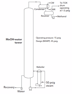
An engineering firm we hired disagrees with me about pressure relief on a methanol/water/formaldehyde column (Figure 1). The company is adamant that we must size and install a relief valve for two-phase flow.
Figure 1. The need for a relief valve is a bone of contention.
The distillation tower operates at about 15 psig and has a design pressure of 45 psig. The tower recovers at the condenser about 99% of the methanol along with a few percent of formaldehyde and water. The methanol gets recycled back to the formaldehyde plant. Some trace vapor travels through 110 ft of 1-in. pipe before passing into a 16-in. vent to a thermal oxidizer (TOX).
After I heard from the firm’s engineer whose analysis indicated the relief valve was necessary, I did a fire-sizing calculation myself and then computed the choked flow for the 1-in. vent from the receiver to the TOX knockout drum. I found the choked flow capacity far exceeds that required for fire sizing. My engineering report disparaged the loss of methanol to the TOX but concluded that no relief valve is needed.
The firm’s relief expert counters that I can’t take a reduction for four inches of fiberglass insulation in a stainless steel jacket; he says fiberglass may burn. Without that reduction, the flow capacity is much greater than the choked flow. Besides, he contends, two-phase flow, not vapor, will exist in the 1-in. vent. He also notes that he must look at other scenarios. Initially, he challenged my engineering report by mentioning the vent line could have an isolation valve — thus, necessitating a relief device. However, the line to the knockout drum doesn’t have a valve. He also stated the relief must be on the tower, not the receiver.
In addition, the expert says the vent system might not be capable of handling the flow of all the vessels connected to it if a site-wide fire occurred. I told him we don’t assume the entire site is on fire to size a vent for a relief flow.
What do you think? Do we need a relief valve on this distillation tower? Is the 1-in. vent adequate? Are there any other scenarios worse than a pool fire that could result in a large relief flow? Is two-phase flow in the vent likely or is it just something the experts wants to consider to reinforce his argument?
Send us your comments, suggestions or solutions for this question by July 12, 2019. We’ll include as many of them as possible in the August 2019 issue and all on ChemicalProcessing.com. Send visuals — a sketch is fine. E-mail us at [email protected] or mail to Process Puzzler, Chemical Processing, 1501 E. Woodfield Rd., Suite 400N, Schaumburg, IL 60173. Fax: (630) 467-1120. Please include your name, title, location and company affiliation in the response.
And, of course, if you have a process problem you’d like to pose to our readers, send it along and we’ll be pleased to consider it for publication.


