The different combinations available can make selecting the right pH sensor for your particular needs seem overwhelming. Because pH measurement points within a process vary, a sensor suitable for one application may not work well elsewhere in the plant or provide the same operational life there. This article discusses some important items for determining the optimal sensor for the process.
The first thing to remember is that a complete pH sensor consists of four mandatory elements: temperature electrode; solution ground; pH measuring glass electrode; and reference electrode. These elements either can be individual electrodes or combined into one sensor body. For a better understanding of the different options available and where one option better suits an application than another, you should consider the individual parts independently.
Temperature Electrode and Solution Ground
These are the simplest components of a pH sensor. A temperature electrode is essential to accurately and automatically compensate for temperature variations in the liquid being measured and temperature-dependent effects on the contact potentials in the glass and the reference systems.
The existence of a solution ground also is vital. However, in both cases, knowing the materials utilized isn’t that important. Concentrate instead on ensuring the pH measuring glass and reference system used are the best ones for the process conditions.
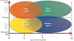
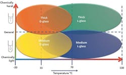
Figure 1. Thickness of the glass as well as its composition determine service range.
pH Measuring Glass Electrode
The correct choice of a glass electrode for a particular application requires knowledge of the components of the measuring loop and their significant properties. Selection must consider not only the “pH glass” chemical makeup but also the mechanical design shape.
Normally, the glass electrode has a bulb-shaped membrane of specific pH glass that is welded to the glass tube. (Alternatives to the standard bulb version of the pH-sensitive glass membranes are available and are better suited for certain process conditions.) The most common bulb constructions are:
Ball shape (shockproof) — universal electrode suitable for most pH applications;
Dome shape (heavy duty) — extremely durable pH membrane (≈1-mm thickness) best suited for measurements in aggressive or abrasive media; and
Flat shape — used in combined sensors for applications involving a considerable solids’ component.
The H+ ions in the liquid being measured interact with the surface (texture) of the pH-sensitive glass to form a stable balance at a specific active H+ concentration. This texture, which provides a high affinity for such a reaction, stems from the specific alkali metal ions used in the composition. Each manufacturer has its own “recipe.”
To facilitate the interaction, the pH-sensitive glass membrane must be “conditioned” by allowing it to absorb a film of water or gel. Conditioning is achieved by soaking the electrode in water for a minimum of 24 hrs. Most sensors come pre-conditioned and can be used immediately without soaking.
The suitability of an electrode depends on its type of glass membrane. Every manufacturer has its own unique formulation; however, some common types of glass are available:
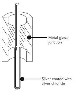
Figure 2. This relies on a silver wire coated with silver chlorine.
• “G” or general-purpose glass is used in processes where the nominal pH value varies around pH 7 and the operating temperature is from -20° to 70°C.
• “L” or chemical-resistant glass is designed for measurements in alkaline media with process temperatures up to 130°C.
• “Na” or sodium glass is utilized where good interaction with alkaline (sodium, potassium, calcium and magnesium) ions, rather than H+, is necessary. This glass serves as the reference element in differential sensors or as the measurement sensor for applications that determine/monitor salt concentration.
Figure 1 illustrates the general applicability of G and L glasses. As it shows, the range of any particular glass type also depends on membrane thickness.
Process conditions greatly influence the chemical resistance of the glass membrane. Elevated temperatures and high salt concentrations (NaCO3 and CaCO3 dissolve the glass) or applications in strongly alkaline liquids generally shorten electrode life. Additives can be included during the manufacturing of the glass to make it more resistant to attack; electrodes suitable for measurements in either strongly acidic or basic liquids can be produced. In aggressive solutions, a heavy duty electrode with a thick dome-shaped glass membrane is preferable.
Reference Electrode
The accuracy of the pH measurement also depends on the properties of the reference electrode, which must be considered to make the correct selection.
A good reference electrode satisfies the following requirements:
• The probe is insensitive to expected changes in the process liquid composition.
• According to Nernst’s Law, the output voltage of the internal reference probe must be the same as the internal reference probe on the pH measuring glass sensor.
• The output voltage is stable.
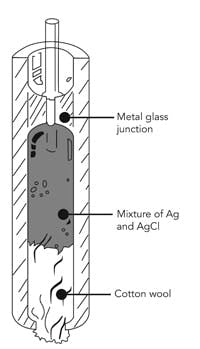
Figure 3. Such a system uses of a paste containing silver, silver chloride and potassium chloride.
Reference electrodes use a variety of reference systems, flow diaphragms and electrolytes.
Generally, reference electrodes rely on a silver/silver chloride-potassium chloride (Ag/AgCl-KCl) system. The reference system consists of a silver wire electrolytically coated with silver chloride (Figure 2). This metal-metal salt combination is dipped in a KCl solution.
An alternative construction more suitable for high-temperature applications dips the silver wire into a paste of Ag, AgCl and KCl (Figure 3). A plug of wadding soaked in KCl seals the paste into a tube. This reference assembly similarly is dipped in a KCl solution.
The electrolyte used in the reference electrode must:
• be chemically inert and neutral;
• have a constant activity of ions;
• be equi-transferent (i.e., the ions of the electrolyte must pass the diaphragm at the same speed); and
• have a low electrical resistance.
The most common electrolytes used in reference electrodes are:1-M KCl solution (with or without gel); 3.3-M KCl solution; and saturated KCl solution. High viscosity KCl solutions suit high-temperature (>70°C) applications.
The conductivity of the 3.3-M KCl electrolyte solution is roughly three times higher than that of the 1-M KCl electrolyte solution. So, the same reference electrode will have a lower reference impedance. The higher conductivity solution is an advantage for some ultrapure water applications that sometimes show a high impedance error when using 1-M KCl. However, it’s important to note that if you’re using a refillable style sensor and change from 1-M KCl to 3.3-M KCl solution, you must recalibrate the sensor. Without recalibration, readings will be off by approximately 0.5 pH.
Junction Issues
Selecting the correct type of junction for a reference electrode also is important because the junction maintains contact between the reference system in the electrode and the process liquid. The choice depends on the process conditions under which the electrode must function. The process liquid must not penetrate the electrode because this could cause poisoning and unstable reference potential.
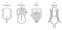
Figure 4. The conditions under which the electrode must function determine the most suitable choice.
Figure 4 shows the four available types of junction: two versions of ceramic, polytetrafluoroethylene (PTFE), and glass-sleeve capillary element. In the first two types, the KCl solution flows slowly into the process. The flow rate depends on the overpressure in the electrode and the process temperature. The electrolyte flow rate rises with increasing temperature.
Non-flowing reference electrodes with a porous PTFE junction suit many dirty liquid applications. The dirt-resistant properties of PTFE will prevent complete fouling of the diaphragm.
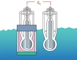
Figure 5. Internal electrode in reference electrode makes contact with process via a salt bridge chamber.
Note: Reference Electrode (left) and Measuring Electrode (right)
However, with very dirty liquids, a glass-sleeve capillary element is preferred because of its larger flow surface. The sleeve easily can be cleaned by first moving the ground ring upwards and then wiping the ground faces.
To provide a stable reference value, the electrolyte in the reference electrode must not be changed by penetration of the process liquid. However, some applications contain ions — e.g., mercury (Hg2+), copper (Cu+), lead (Pb2+) and silver (Ag+) — that will react with the KCl solution if process ingress occurs. The leads to an internal differential that results in errors in pH measurements.
Solving this problem requires separating the KCl solution and the process liquid using a double junction electrolyte, resulting in a reference electrode with a built-in salt bridge.
Processes containing cyanides, bromides, iodides or sulfides are a second example of where selecting the KCl solution is critical. (Many biological process liquids contain sulfur compounds.) In most cases, a black diaphragm indicates the reference electrode lacks a double junction. The black is a deposit of silver sulfide in or directly after the flow diaphragm.
Such deposits can result in:
• long response of the pH measuring circuit;
• non-reproducible diffusion voltages and, consequently, drift in the indication;
• extreme difficulty in calibration (because the formed diffusion voltage can be pH dependent); and
• increased resistance of the diaphragm (slower measurement).
In processes with pressure variations, the composition of the electrolyte may change as a result of process liquid penetration into the electrode. Such a change may cause a measurement error or even poisoning of the reference system of the electrode. To alleviate this problem, consider an electrode with an integral pressure-compensation system. Various designs exist but ones using a bellows are most common.
In that design, a compressed bellows is positioned within the electrolyte vessel of the electrode. One side of the bellows is connected to the outside pressure via a ceramic junction. The pressure inside the bellows equals the pressure outside; only the elasticity of the bellows itself causes the over-pressure that results in a flow of electrolyte. When the bellows is fully expanded, the electrolyte is exhausted and refilling is required. The bellows must be compressed before refilling.
Pressure-compensated systems also can be used in processes with pressures below atmosphere; some designs can allow for 360° mounting capabilities.
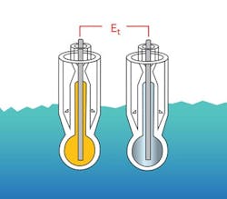
Figure 6. The reference portion in the reference electrode is made completely of glass.
Note: Reference Electrode (left) Measuring Electrode (right)
Differential Measuring System
All designs of KCl reference electrodes are susceptible to the process coating or plugging the junction, causing an inaccurate or unstable reference voltage that results in pH measurement errors. Over time, depletion of internal electrolyte and poisoning by the process will affect a standard reference. This issue has led to development of an alternative reference design known as a differential reference system. There are two common approaches:
1. Glass-in-glass (Figure 5). This uses a standard glass electrode as the measuring electrode to generate a potential proportional to the process pH. The second glass electrode serves as the reference electrode and consists of an internal measurement electrode immersed in a stable buffer solution. The internal electrode makes electrochemical contact with the process via a salt bridge chamber (double junction) and generates a standard reference potential. Both glass electrodes have a common potential developed at the solution ground electrode.
This design eliminates the stability problems experienced with conventional references due to process poisoning of the reference element. However, because of the liquid junction interface with the process, plugging and coating problems still can occur.
2. Sodium or cation reference (Figure 6). Its reference portion is made entirely of a glass that provides a mV output corresponding to the sodium or salt (cation) concentration of the process or solution it’s in. Therefore, as the sodium or cation salt concentrations change, so will the reference voltage it generates.
This design avoids many of the challenges encountered in pH applications. There’s no liquid junction to be coated or clogged and no path for the process to affect the electrolyte or the internal Ag/AgCl element. This makes the sensor truly maintenance free.
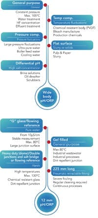
Figure 7. These charts highlight factors that suggest a particular type of sensor for a given application.
Choose Correctly
Careful consideration of the demands of the specific application underpin achieving an accurate, reliable measurement with a sensor that provides reasonable life expectancy while minimizing required routine maintenance. If you’re frequently calibrating or replacing a pH sensor, then there’s a good chance it’s not the right combination for the process. Many general-purpose wide body (all-in-one) electrodes will work very well for many applications. However, some services do better if you choose individual electrodes with unique glass design and reference systems not available in an all-in-one design. Use the quick reference charts in Figure 7 as a best practice guide to find the recommended sensor based on the specifics of a particular application.
CHERLYN MARLOW is product manager, process liquid analyzers, for Yokogawa Corp. of America, Newnan, Ga. MIRANDA DE BRUIJN is product manager, process analyzers, for Yokogawa Europe B.V., Amersfoort, the Netherlands. Email them at [email protected] and [email protected].
