Most processes are multivariable and, thus, need a control configuration with two or more loops. The typical starting point is a single-loop configuration that relies on proportional-integral-derivative (PID) controllers, the justification being “keep it simple.” These usually deliver adequate performance but occasionally interaction between the loops renders one or more loops “untunable.”
Model predictive control (MPC) performs very effectively in applications plagued by interaction. Process optimization normally is required to provide the economic benefits to justify installing and supporting an MPC application. For applications within the main process, benefits of optimization often suffice. However, this is far less likely in auxiliary parts of the process.
The alternative is to insert simple elements such as characterization functions and summers into the control configuration to reduce the degree of interaction to the point where the loops can be tuned successfully [1]. The result is advanced regulatory control; its objective is to maintain the key process variables at or near their targets. The control configuration provides no optimization. However, by reducing the variance in the key process variables, it can enable operating the process closer to the constraints, with ensuing benefits.
For such configurations to be accepted in a production facility, they must comply with the following requirements [2]:
1. Process operators must be able to take control of any final control element and specify its opening. When a summer block or the like is inserted between the output of the PID and the final control element, the customary approach of switching the PID controller to manual and specifying its output isn’t satisfactory.
2. All transitions between the manual and automatic modes of operation must be smooth or “bumpless.” Achieving this requires proper configuration of output tracking.
3. One or more final control elements may be driven to a limit. So, the configuration must prevent reset windup in a PID controller.
These issues are the primary focus of this article. However, first, let’s start by describing the process, illustrating the tuning problem for the single-loop configuration, and formulating a revised configuration.
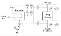
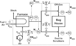
Figure 1. Operation relies upon a single-loop control configuration.
Off-Gas Process
Figure 1 depicts a process to remove contaminants from an off-gas stream that contains particulate matter, sulfur dioxide (SO2), and sufficient water vapor that the dew point is above the ambient temperature. The bag house eliminates the particulate matter and then scrubbers remove the SO2. Because condensate would be acidic, temperatures must remain above the dew point until the off-gas stream arrives at the scrubbers.
A furnace containing a heat exchanger produces a hot air stream. (The products of combustion don’t enter the process.) Sufficient hot air is added upstream of the bag house to keep the off-gas stream above its dew point through the bag house. Additional hot air is added downstream of the bag house so the off-gas stream remains above its dew point until it arrives at the scrubbers.
In 1976, Trevathan used such an off-gas process in an article on process control as practiced in the chemical industry [3]. That paper included a simple flowsheet along with a very brief description of the process but provided no values for flow rates, temperatures, equipment sizing, etc. The parameters we’ll use have no relationship to Trevathan’s process but, like Trevathan, our results will come from a simulation of the process.
Single-Loop Control Configuration
The control configuration shown in Figure 1 reflects the customary approach of “control every variable with the nearest valve.” The appropriate order for tuning the controllers is:
Hot air pressure controller (PC). This loop can be tuned without the furnace in operation. The loop responds very rapidly, the dynamics being dominated by the 10-sec travel time for all dampers.
Hot air temperature controller (TC). The thermal capacity of the furnace makes this loop significantly slower.
Bag house inlet TC. This temperature results from mixing two gas streams. Mixing processes respond quickly.
Scrubber duct inlet TC. This temperature also results from mixing of two gas streams.
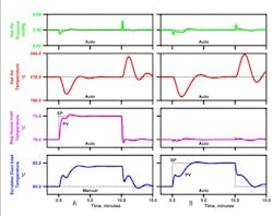
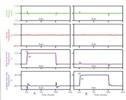
Figure 2. Charts show results of tuning the bag house inlet TC while the scrubber duct inlet TC is on manual (a) and on automatic (b).
Figure 2(a) presents the results of tuning the bag house inlet TC using this order. The scrubber duct inlet TC is on manual; all others are on automatic. The bag house inlet temperature reflects the fast dynamics of a mixing process.
Figure 2(b) presents the results of tuning the scrubber duct inlet TC. All other loops are on automatic. The scrubber duct inlet temperature initially exhibits a rapid response consistent with the dynamics of a mixing process. However, the rapid response is short-lived. Changing the opening of the hot air damper also affects the hot air temperature, which in turn impacts the scrubber duct inlet temperature. The effect is slower and reflects the dynamics of the furnace.
Although some aspects of the bag house inlet temperature response in Figure 2(a) are unusual, the performance is acceptable. However, the performance of the scrubber duct inlet temperature in Figure 2(b) isn’t.
Analysis of Tuning Issues
On an increase in the set point for the scrubber duct inlet temperature, the controllers in Figure 1 respond as follows:
Scrubber duct inlet TC. The controller opens the hot air damper to scrubber duct inlet.
Bag house inlet TC. Opening the hot air damper to scrubber duct inlet “steals” some hot air from the bag house inlet, which decreases the bag house inlet temperature. The controller opens the hot air damper to bag house inlet.
Hot air PC. Opening the two hot air dampers reduces the hot air pressure. The controller opens the fresh air damper.
Hot air TC. Opening the fresh air damper lowers the hot air temperature. The controller opens the fuel gas valve.
Adding additional heat to the furnace increases the scrubber duct inlet temperature. The usual conclusion: the configuration in Figure 1 will function properly.
Even when the steady-state cause-and-effect relationships are reasonable, dynamic issues can lead to performance problems. The issues here are similar to those for the outer and inner loops of a cascade — the configuration performs properly only if the inner loop is faster than the outer loop, preferably by a factor of five. This requirement generally also applies to other configurations in which one loop depends on another. If a slow loop relies on a fast loop, the configuration performs as expected. However, if a fast loop relies on a slow loop, performance issues arise.
For the configuration in Figure 1, the scrubber duct inlet TC (a fast loop that involves mixing two streams) relies on the hot air TC (a slow loop that reflects the dynamics of the furnace). Such dependencies lead to the unusual responses in Figure 2.
Understanding The Process
The scrubber duct inlet temperature loop in Figure 1 has issues. Gaining a proper understanding of them must start with examining how the process responds to opening the hot air damper to scrubber duct inlet when all controllers are on manual.
Opening the damper increases the hot air flow through the damper. This additional hot air comes from some combination of the following:
• Hot air is “stolen” from bag house inlet. The temperature of the off-gas entering and exiting the bag house is lower.
• Fresh air flow increases. With a constant heat input to the furnace, the hot air temperature decreases.
Thus, while more hot air is flowing to the scrubber duct inlet, the off-gas exiting the bag house and the hot air flowing through the hot air damper are cooler.
A simple statement of the energy balance requires that the heat from combustion of the fuel (flow × heating value × furnace efficiency) must equal the heat needed to increase the temperature of the combined fresh air flow and off-gas flow to the scrubber duct inlet temperature. (Technically, the bag house incurs a small but negligible heat loss.)
For a constant heat input to the furnace, the steady-state energy balance suggests the following behavior:
Fresh air damper. Increasing the fresh air flow slightly decreases the scrubber duct inlet temperature.
Hot air dampers. Diverting air from upstream of the bag house to downstream (or vice versa) minimally affects the scrubber duct inlet temperature.
Only the fuel gas valve has a significant long-term effect on the scrubber duct inlet temperature.
With all controls on manual, the hot air damper to scrubber duct inlet nominally impacts the scrubber duct inlet temperature. The scrubber duct inlet temperature loop in Figure 1 relies on the other loops to function, the result being the responses in Figure 2(b).
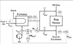
Figure 3. A summer adds the feedback trim to the ideal value to determine the actual fresh air damper opening.
Revised Control Configuration
Consider using the fuel gas valve to control the scrubber duct inlet temperature. The “control each variable with the nearest valve” rationale suggests this valve is “too far away” for effective control. Dynamically, the hot air damper to scrubber duct inlet quickly affects the scrubber duct inlet temperature — but this is only a transient impact with minimal long-term effect. The fuel gas valve affects the scrubber duct inlet temperature more slowly but with a significant long-term effect.
Any change in the fuel flow to the furnace should be accompanied by a change in the fresh air flow. Ratio control is well-known [2], the objective being to maintain a constant ratio of fresh air flow to fuel gas flow. However, because no flow meters are installed, the ratio logic must rely on a characterization function that relates fresh air damper opening to fuel gas valve opening at steady-state conditions.
The data points for the characterization function, which is developed for a specified hot air temperature and pressure, must come from tests conducted on the process. Pressure affects the flow through the various dampers. To eliminate this source of error in the characterization function, control of hot air pressure is essential.
Figure 3 presents control logic that provides the following functions:
1. The scrubber duct inlet TC output (MSDI) is the fuel gas valve opening. The lower output limit should be 30% (which approximately corresponds to minimum fire).
2. The output f(MSDI) of the characterization function (the “TY” element) is the “ideal” value for the fresh air damper opening.
3. The summer adds the feedback trim to the ideal value to obtain the actual fresh air damper opening.
4. The hot air TC adjusts the feedback trim to attain the desired hot air temperature.
The hot air TC must be able to obtain a fresh air damper opening that is slightly larger or slightly smaller than the value from the characterization function. Positive and negative values must be possible for the feedback trim.
For advanced regulatory controls, controller outputs preferably are expressed in engineering units. So, we’ll use “% open” for all valve openings. An output range of -100 to +100% open permits the hot air TC to drive the fresh air damper fully open or fully closed, regardless of the output of the characterization function.
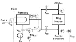
Figure 4. This system incorporates two additional controllers — a PC for hot air output and a TC for the bag house inlet.
Hot Air Dampers
The hot air dampers must be used to control both hot air pressure and bag house inlet temperature.
While the hot air pressure could be regulated by adjusting the opening of either hot air damper, doing so would upset the bag house inlet temperature. Providing the capability for the hot air PC to change the openings of both hot air dampers will reduce this disturbance.
Consider treating the controller outputs as follows:
MHAA = Output of hot air PC: arithmetic average of the openings of the two hot air dampers. The output range of the hot air PC should be the customary 0–100% open.
MHAD = Output of bag house inlet TC: difference in the openings of the two hot air dampers, specifically the opening of the hot air damper to bag house inlet minus the opening of the hot air damper to scrubber duct inlet. You must allow MHAD to be positive (hot air damper to bag house inlet more open than the hot air damper to scrubber duct inlet) or negative (hot air damper to bag house inlet less open than the hot air damper to scrubber duct inlet). An output range of -100 to +100% open is required.
The control configuration in Figure 4 obtains the openings of the respective hot air dampers (YBHI and YSDI) by incorporating a summer for each damper:
• Hot air damper to bag house inlet: YBHI = MHAA + ½ MHAD; and
• Hot air damper to scrubber duct inlet: YSDI = MHAA - ½ MHAD.
Figure 5 illustrates the performance of the alternative control configuration with all controllers on automatic. Figure 5(a) shows responses to a change in the set point for the bag house inlet TC to 75°C from 70° and back. Figure 5(b) shows responses to a change in the set point for the scrubber duct inlet TC to 85°C from 80° and back. Both loops implement the set point changes very expeditiously.
We can view the configuration in Figure 4 as a “poor man’s decoupler.” Three of the controllers are adjusting two final control elements:
Scrubber duct inlet TC. Openings of fuel gas valve and fresh air damper increase or decrease to change the hot air flow at a constant hot air temperature.
Hot air PC. Openings of the hot air dampers increase or decrease to maintain the same hot air distribution upstream and downstream of the bag house.
Bag house inlet TC. Openings of the hot air dampers change in opposite directions to minimize the effect on hot air pressure.
This configuration doesn’t completely eliminate the interaction among the four control loops but reduces it sufficiently that the loops perform satisfactorily.
Unfortunately, no design methodology is available for developing the configuration in Figure 4. Trevathan in 1976 noted a lack of technology to incorporate such approaches [3]; this still remains true. To come up with such a configuration, you must rely on a basic understanding of the behavior of the process.
Manual Control
In industrial plants, process operators must be able to intercede to specify the opening of a final control element. When a controller outputs directly to a final control element, this means they must switch the controller to manual and then change the controller output.
For the control configuration in Figure 4, this approach only can be used for the scrubber duct inlet TC. All other controllers output to a summer block whose output determines the opening of the final control element.
Most digital controls provide a so-called “valve block” whose primary function is to convert the input in % open to the output value required by the final control element. Most valve blocks also offer two modes of operation:
Remote. The input to the valve block specifies the % open for the final control element.
Local. The process operator specifies the % open for the final control element.
As with all forms of digital technology, other approaches to providing manual control are possible.
Switching the hot air TC to manual isn’t equivalent to switching the fresh air damper to local. The difference is:
Hot air TC on manual. The ratio logic continues to function. Changes in the fuel gas valve opening are translated to changes in the fresh air damper opening. The scrubber duct inlet TC effectively is varying the hot air flow at a constant hot air temperature.
Fresh air damper valve block to local. The ratio logic ceases to function. The fresh air damper opening doesn’t change when the fuel gas valve opening changes. The scrubber duct inlet TC effectively is varying the hot air temperature at a constant hot air flow.
With regard to the hot air, switching the fresh air damper to local changes the manner of operating the off-gas process from variable flow, constant temperature to variable temperature, constant flow. The different behavior can have consequences.
For the scrubber duct inlet temperature loop, the process gain is the sensitivity of the scrubber duct inlet temperature to the fuel gas valve opening. The basis for the sensitivity depends on the remote/local status of the fresh air damper:
Fresh air damper on remote: sensitivity of scrubber duct inlet temperature to fuel gas valve opening at a constant ratio of fresh air flow to fuel gas flow.
Fresh air damper on local: sensitivity of scrubber duct inlet temperature to fuel gas valve opening at a constant fresh air flow.
The latter sensitivity is larger than the former. Switching the fresh air damper to local abruptly increases the process sensitivity. This rise in sensitivity makes the scrubber duct inlet temperature loop more oscillatory. For the hot air process, the loop is stable but with excessive oscillations.
The opposite effect also is possible. That is, switching the valve block for a final control element to local could cause a loop to respond so slowly that it effectively ceases to function.
Another useful function of a valve block is to impose limits on the output value. Fully closing the fresh air damper makes no sense — no fresh air means no hot gas. For the fresh air damper valve block, the output range would be 0–100% open but the output limits, for example, could be 20 and 100% open. With the summer inserted between the output of the hot air TC and the fresh air damper, imposing a minimum damper opening by specifying the lower controller output limit for the hot air TC isn’t effective.
Figure 5. Charts show the impact of changes to the set point of the bag house inlet temperature (a) and the scrubber duct inlet temperature (b).
Bumpless Transitions
When the operator assumes manual control of a final control element, control no longer is possible for one of the controlled variables. So, a smooth or bumpless transition between manual and automatic control is essential.
When the output of a PID controller directly drives a final control element, the standard features provided by process control systems ensure that all transitions are bumpless. However, when blocks such as summers are inserted between the output of the PID controller and the final control element, you must properly configure output tracking to achieve bumpless transitions.
Configuring output tracking requires a condition and value for tracking. For the hot air TC, the specifications are:
• Condition: fresh air damper on local; and
• Value: fresh air damper opening YFA minus the characterization function output f(MSDI).
When output tracking is active, the controller output is set to the specified value, the normal control calculations are suspended, and the PID control equation is initialized (the same as for a manual-to-automatic transition).
You can regulate hot air pressure using either of the hot air dampers. The following approach retains control of the hot air pressure preferential to the bag house inlet temperature:
Bag house inlet TC:
• Condition: either hot air damper on local; and
• Value: difference in hot air damper openings.
Hot air PC:
• Condition: both hot air dampers on local; and
• Value: average of hot air damper openings.
Table 1 presents the configuration for output tracking.
Table 1. It is essential to specify a condition for tracking and a value for tracking.
The desire to preferentially retain control of one variable over another isn’t unique to the off-gas process. In most double-end composition control applications, one composition pertains to a saleable product while the other relates in some manner to operational efficiency. Most plants are more concerned about the saleable product.
Preventing Windup
Reset windup commences whenever changes in a controller output have no effect on the measured variable for that controller. For most PID loops, preventing reset windup only requires specifying appropriate values for the controller output limits. For the control configuration in Figure 4, this is the case for the scrubber duct inlet TC. The output of this loop is the fuel gas valve opening, so the values for the output limits should correspond to the maximum and minimum openings permitted for the fuel gas valve.
For each of the other three loops, the controller output is an input to a summer whose output is the opening of a damper. The value of the controller output that corresponds to the maximum and minimum openings of the damper depends on the value of the other input to the summer. In such cases, you must configure either external reset, integral tracking or inhibit increase/inhibit decrease (also called one-direction control) [2].
Let’s look at integral tracking.
For the hot air temperature loop in Figure 4, the output of the hot air TC is added to the output of the “TY” element to obtain the fresh air damper opening. Suppose the output limits for the fresh air damper opening are 20 and 100% open. If none of the above features are properly configured for the hot air TC, windup will occur under the following conditions:
Damper driven fully open. The hot air TC will continue to increase its output until it attains the upper controller output limit for the hot air TC.
Damper driven to 20% open. The hot air TC will continue to decrease its output until it attains the lower controller output limit for the hot air TC.
Configuring integral tacking requires a condition for tracking and a value for tracking. To prevent reset windup in the hot air TC, integral tracking must be configured as follows:
• Condition: fresh air damper driven to either limit; and
• Value: fresh air damper opening YFA minus characterization function output f(MSDI).
The hot air dampers potentially can be driven fully closed or fully open. The integral tracking specifications pertaining to the hot air dampers are similar to those for output tracking:
Bag house inlet TC:
• Condition: either hot air damper is at a limit; and
• Value: difference in hot air damper openings.
Hot air PC:
• Condition: both hot air dampers are at a limit; and
• Value: average of hot air damper openings.
Table 2 presents the configuration for integral tracking that preferentially retains control of hot air pressure over bag house inlet temperature.
Table 2. This configuration preferentially retains control of hot air pressure over bag house inlet temperature.
CECIL L. SMITH is president of Cecil L. Smith, Inc., Houston. E-mail him at [email protected].
LITERATURE CITED
1. Smith, Cecil L., “Practical Process Control: Tuning and Troubleshooting,” John Wiley and Sons, Hoboken, N.J. (2009).
2. Smith, Cecil L., “Advanced Process Control: Beyond Single Loop Control,” John Wiley and Sons, Hoboken, N.J. (2010).
3. Trevathan, V., “Process Control in the Chemical Industry,” AIChE Symp. Ser., Vol. 72, No. 159, p. 40 (1976).
