Safety and productivity at process plants suffer because too many engineers believe myths concerning design, implementation and operation of safety instrumented systems (SISs). So, let's dispel the leading myths.
1. Using certified equipment and personnel ensure a safe system. The IEC 61511 international standard doesn't even use the word "certified." There's no requirement for certified equipment or personnel. However, a lot of companies sell safety certification services for both equipment and personnel.
It's important to remember that certification is no substitute for experience, specifically prior-use history for equipment and project background for personnel. Many mistakenly seem to think that taking a certification class makes them an instant expert in the safety lifecycle. Questions and comments on safety discussion lists posted by certified but inexperienced people underscore this fallacy on a weekly basis. Likewise, buying parts with certification to a SIL 3 Claim Limit isn't sufficient to fulfil SIL 3 requirements for a safety function.
For field equipment, the selection guidance in ISA-TR84.00.04 Annex L emphasizes the importance of understanding how well equipment works in the operating environment under its specific mechanical integrity (MI) program. Certified equipment may appear acceptable but you can't assume it will perform dependably in the field.
Simply put, certification is no substitute for experience.
2. Failure detection is more important than failure prevention. The IEC 61508 international standard emphasizes the need to identify and correct dangerous failures that increase the potential for an incident or a near-miss — but short-changes failure prevention. While detecting failures is extremely important, a better approach is to design the SIS with a low total failure rate. This minimizes work orders, spurious trips and the effort required to restore normal operation.
IEC 61508 favors equipment with high diagnostic coverage over equipment with a low failure rate. If Device A has a mean time between failures (MTBF) of 5,000 years with all its failures being dangerous undetected, and Device B has a MTBF of 5 years with 99.9% diagnostic coverage, the IEC 61508 Safe Failure Fraction calculation would indicate that Device B as better.
Thus, IEC 61508 rewards equipment for failing detected rather than working. The failure rate of Device A would meet SIL 3 with minimal spurious trips but, because of its low safe failure fraction, it couldn't be certified above SIL 1. Device B would generate many work orders and significantly increase the potential for spurious trips but could be certified to SIL 3 due to its high safe failure fraction.
Go ahead and use Device A in an SIL 3 function if it is the right device for your process.
3. Vendor-supplied diagnostics can detect all dangerous failures. Often vendor-supplied diagnostics only apply to electronic failure and not to process interfaces. Some diagnostics can detect special conditions like magnetic-flow-meter probe coating.
Unfortunately in most cases, you can't know whether the vendor diagnostics are even working because there're no means to test them. Verification and validation of vendor diagnostic claims and associated data is currently a topic under discussion at the IEC 61511 and ISA-TR84.00.03 working group meetings.
The best diagnostics are those you implement independently to verify the process connection and field device are working from a total system and application perspective. No matter the diagnostic, the only way to be certain that an SIS device is working is to proof test it.
4. Partial testing is good enough. Partial testing only identifies specific failure modes of equipment. It's not a substitute for a complete function check that proves the equipment does what it needs to do as and when required. Major process industry incidents have shown that what you don't maintain eventually fails.
For example, the "push-to-test" feature on some electronic sensors only checks the electronics and doesn't determine whether the sensing elements are working properly. Partial stroke testing validates the valve actuator but not the ability of the valve to close fully or to meet leak tightness requirements. Partial tests can detect some failure modes. You must perform full proof testing, though, to demonstrate the specified operation of the equipment.
5. The main purpose of proof testing is failure detection. Unfortunately, IEC 61511 has encouraged this concept because it defines a proof test as an opportunity to detect dangerous undetected failures. However, detection isn't the primary goal of proof testing — its main purpose is finding weaknesses in your MI strategy and triggering root-cause identification with subsequent change in the specification, design, installation or strategy. You should consider any failure found in a proof test as a serious problem, requiring immediate investigation to prevent future failures.
Many incident investigations point out that a company had found and repeatedly corrected failures prior to an incident — but didn't prevent the failure from re-occurring by determining and addressing the root cause.
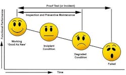
6. Proof testing suffices to ensure mechanical integrity. The proof test only validates MI, which depends upon inspection and preventive maintenance (Figure 1).
You should perform periodic inspections to identify and correct incipient issues and degraded conditions; this often is called proactive or condition-based maintenance. You can conduct some inspections externally during operation but others require more-rigorous internal inspection, such as looking at a valve seat or pulling wires to see if they're loose.
Also, perform regular preventive maintenance to replace parts with a shorter life expectancy than the major equipment components. This reduces the failure rate and extends the useful life of the equipment.
Proof testing demonstrates the MI plan consisting of inspection and preventive maintenance suffices to sustain the equipment in the "as good as new" condition.
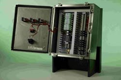
7. Relay-based safety systems aren't as good as safety programmable logic controllers (PLCs). Relays have extensive prior-use history in many industry sectors, very low failure rates, and readily predictable and well-understood failure modes. Relays can be installed locally with no need for climate-controlled enclosures (Figure 2).
Safety PLCs are more flexible and easier to modify — but this often leads to ad hoc programming. Without a detailed application program specification, a rigorous software development process and extensive testing, safety PLC programs can have significant undetected problems.
While safety PLCs have extensive diagnostics, this is largely because they have many components that can fail. Simplex safety PLCs have overall failure rates an order of magnitude greater than those of relays, and so need diagnostics and hardware fault tolerance to offset these higher rates.
You can expand a safety PLC to protect an entire facility or implement multiple distributed PLCs. Covering the facility with one does yield the lowest cost per I/O point; however, it also means putting all your eggs in one climate-controlled basket. A safety PLC failure could put the whole plant at risk. In addition, necessary maintenance or testing potentially could impact the entire production unit.
Relays support a cost-effective distributed safety system that can be local to the specific equipment being controlled and monitored. Maintenance and testing of distributed safety systems only affect the local equipment these systems are designed to protect.
8. Application programming for modern safety PLCs is so easy that anyone can do it. With drag-and-drop interfaces, function blocks and some training, almost anyone can program a PLC in some fashion. But translating critical safety logic into the PLC application program requires close cooperation among programmers, process control engineers, and operations and maintenance personnel.
This cooperation should include an upfront program specification agreed to by all prior to PLC programming. A non-existent or poorly documented application program specification can lead to badly executed programming with a significant negative impact on the risk reduction due to systematic failures. Disorganized and complex programming yields an application program that's difficult to understand, properly test and safely modify.
9. Only process safety must be under a management system that ensures its integrity. Regulations for the protection of workers and the public mandate safety measures. No directives govern equipment protection or overall loss prevention — so, companies view such efforts as an optional business decision. However, a major non-safety-related event often can pose potential danger to personnel and equipment just like a safety-related one. Even when a non-safety-related event doesn't result in injury, a company can incur devastating losses from business interruption, equipment damage, repair costs, harm to its reputation, and disruption of supply to customers.
Compressors, pumps, heaters and boilers have many shutdown systems intended to prevent losses. While these systems aren't specifically covered by IEC 61511, you still should design and manage them to lower risk of a loss. IEC 61511 recognizes this benefit in Clause 1k, stating that it may be applied in non-safety applications such as asset protection. Where the equipment is process-critical, it's best to opt for a conservative design and use low-spurious-trip architectures.
Leading companies have found that comprehensively examining all potential losses and following sound loss-prevention practices generate value to their stakeholders.
10. As long as the SIS is designed to fail-safe, the design is optimal. This concept became prevalent after the issuance of IEC 61511, which focuses on the safety aspects of the instrumentation design and management. The standard's concentration on failing safe is appropriate given its underlying purpose to support worldwide process safety regulations — but reliability is just as important as safety for many chemical processes.
Plant operators need trustworthy and reliable instrumentation. Many incidents have occurred because operators ignored information from instruments they perceived to be untrustworthy or because unreliable instruments had been bypassed to keep a process online.
The Center for Chemical Process Safety's "Guidelines for Safe and Reliable Instrumented Protective Systems" (CCPS IPS) considers reliability a key factor for process safety instrumentation. This book advises treating reliability as equal in importance to IEC 61511's safety integrity for instrumented systems.
11. If the SIS is configured to alarm on detected failure, the process is safe as long as repair is completed within the assumed mean time to repair. An inherently safe design configures detected failure toward the trip condition and uses redundancy to achieve reliability. Configuring an SIS to alarm often increases the risk of loss of containment by at least an order of magnitude, because the SIS either is degraded in the case of a fault-tolerant SIS or disabled when no fault tolerance is provided.
IEC 61511, ISA-TR84.00.04, and CCPS IPS discuss the use of compensating measures to temporarily manage the risk. Recognize that the fault repair and compensating measures often result in higher occupancy and a greater likelihood that ignition sources are present. This increases the potential consequence severity should an incident occur during repair — so conduct a hazards and risk assessment to review and approve the choice to configure detected faults to alarm.
The requirement for safe operation demands covering the risk gap from the time of failure discovery until the fault is corrected and equipment returns to service. You must address continued process operation with a degraded or disabled SIS via procedures that define the compensating measures sufficient to maintain safe operation.
12. If a process hazard analysis (PHA) indicates that risk criteria have been met, the process is safe. The hazardous events identified during the PHA are limited by the evaluation team's assumptions, which are restricted by their collective experience, knowledge and available information. Any risk estimate is limited by the quality assurance and the feedback process that ensures the data are relevant in the real world; bias potentially can creep in.
A 2005 analysis of incident data by the U.K.'s Health and Safety Executive determined that more than one in four hazardous events were attributed to poor hazard and risk assessment and follow-up. A 2003 analysis by the U.K.'s Health and Safety Laboratory found that more than one in three incidents that occurred due to process deviations from normal operation weren't adequately considered as potential hazards or causes of equipment failure.
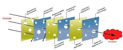
Quality design and management practices are absolutely essential to achieve real risk reduction and incident prevention. Without continuing efforts, latent conditions appear over time, causing failures in the safety layers like holes in Swiss cheese. Without proactive action, the holes may eventually align to present a challenge to safe operation when process deviation occurs (Figure 3).
13. An acceptable probability of failure on demand average (PFDavg) is sufficient proof of a safe system. The PFDavg is only as good as the model of the safety system and the data used for calculations. Most safety professionals can perform the calculations with a good tool — but in many cases experience and expertise are needed to see the forest for the trees. Failure rate data often come with large associated uncertainty. Correctly modeling the functions and applying the data require good engineering judgment. The usual, almost-exclusive focus on the sensor, logic solver and final element leads many to discount other potentially important contributors to failure. The PFDavg calculation must include all equipment that can cause a failure to function as specified.
Vendor data alone don't suffice to determine PFDavg. Vendor failure rates assume perfect operating conditions and perfect MI, ignoring the process' and operating environment's contribution to equipment degradation and failure. Actual failure rates highly depend on the operating environment and MI, and can be orders-of-magnitude higher than vendor reported rates. Consequently, you should base reliability data on field feedback — the less the feedback, the more the uncertainty in the data.
Draft revisions of ISA-TR84.00.02 and ISA-TR84.00.03 encourage development of user databases to formalize actual operating experience and feedback. IEC 61511 Clause 5.2.5.3 requires evaluating SIS performance in the operating environment against assumptions made during design. In the absence of detailed feedback data, you should be more conservative when verifying SIL ratings, and shouldn't use the PFDavg calculation to supersede the fault tolerance requirements of IEC 61511 or good engineering judgment.
14. The basic process control system (BPCS) and the SIS can be easily and safely combined into one system. It's possible but there are many caveats because sharing BPCS equipment with the SIS violates inherently safer principles. IEC 61511 Clause 11.2.4 states that unless the BPCS is qualified in accordance with the standard, the SIS must be separate and independent from the BPCS. Qualifying the BPCS to IEC 61511 is more detailed than SIL verification, hazard rate analysis or calculations. ISA-TR84.00.04 Annex F and IEC 61511 Part 2 provide numerous reasons for not combining the systems.
Justifying the sharing of equipment requires carrying out additional failure and security analysis to ensure the overall hazard rate can be met for random failures and to provide adequate fault tolerance for systematic failures. Equipment also must have a prior-use history that demonstrates its dependability in both applications.
Independent and separate systems reduce common-cause, common-mode and systematic failures — and minimize the impact of BPCS failure on the SIS. Separate systems also ease making changes, performing maintenance, testing and documenting the SIS.
Separate systems facilitate identifying and managing the SIS elements and, thus, simplify and clarify validation and functional safety assessment. They support access security and enhance cyber security for the SIS because revisions to BPCS functions or data don't impact it. Finally, separate systems reduce the amount of analysis needed to ensure the SIS and BPCS are properly designed, verified and managed.
Common systems can reduce training — but ultimately not design, operations and maintenance manpower requirements for the reasons stated above.
15. The BPCS can serve as a process safety defense for risk reduction without a management system. Regulations as well as insurance and industry practices generally demand that all safeguards or protection layers have a management system to ensure proper operation when needed.
A safeguard implemented in BPCS hardware is no different than one implemented in the SIS; it must be covered by specification and MI, both with associated management systems. Upcoming publications from CCPS and ISA will provide detailed requirements in this area.
16. BPCS and SIS independence is a simple matter. You must demonstrate independence in the hardware, software, and personnel and management systems.
Any hardware or software the BPCS and SIS share could possess dangerous failure modes that make both systems vulnerable. Such modes could affect the ability of the common hardware and software to operate as required for both functions.
In terms of personnel and management, you must examine the entire lifecycle to see where shared personnel and management procedures, especially in the areas of design and maintenance, could contribute to systematic failure.
17. Safety systems aren't as important as the BPCS. Many companies spend a great deal of time and effort trying to justify that certain safety instruments, valves and other components aren't required. Such arguments rarely arise when it comes to the BPCS.
It's important to remember that the investment in safety systems is very small compared to that in the BPCS, and nearly negligible compared to that in the process equipment. Yet, the safety systems are the most dependable means to protect the total investment.
Proper design and management can yield effective and reliable safety systems. Leading companies have found that comprehensively examining their overall BPCS and safety strategy reveals opportunities to reduce unplanned events and emergency work orders, improving safety and productivity.
ANGELA E. SUMMERS, P.E., Ph.D., is president of SIS-TECH Solutions, LP, Houston. E-mail her at [email protected].


