Workplace Safety: Understand the Shocking Truth
Engineers and safety professionals at plants must work long and hard to eliminate the possibility of fires or explosions in areas where flammable or combustible materials are being processed, handled or stored. This involves identifying all potential ignition sources — whether electrical, hot surfaces, mechanical sparks or naked flames.
However, no matter how well the working environment has been designed, there's one potential source of spark discharges that's ever-present in virtually every workplace and that has enough energy to ignite all common flammable or combustible liquid vapors and gases as well as many airborne dusts and loose solid materials. That energy source is static electricity, also known as "electrostatic" or just simply "static."
Static electricity is the prime culprit for at least two serious fires or explosions in industry worldwide every day of the year, according to the National Fire Protection Association (NFPA) and the U.K.'s Institution of Chemical Engineers (IChemE). In the U.S. alone, static electricity causes on average 280 industrial incidents each year reported to fire and emergency departments, resulting in injuries and fatalities, tens of millions of dollars of direct property damage, lost production or plant downtime, and environmental release issues.
Static electricity is generated continuously through relative motion — in other words, whenever surfaces of materials come into contact and separate. This interaction causes electrons to be stripped from one surface to the other, creating an electrical imbalance. The rate at which electrons are transferred is influenced by a number of factors such as speed and area of contact and the characteristics of the materials (for example, the transfer rate will increase greatly if the materials are dissimilar or one is an insulator). In the workplace typical examples include liquids flowing through pipelines or into drums and tanks, powder dropping down a chute — and even a person walking across an insulating floor. Charge generated in this way often is lost by a combination of conduction to ground and contact with atmospheric moisture (humidity). However, generated charge becomes a serious problem in hazardous areas when it's allowed to accumulate on objects not at ground potential. In these cases, a significant potential (voltage) can develop and, depending on the characteristics of the ungrounded object, this may have many times the surrounding flammable atmosphere's minimum ignition energy (MIE), the minimum energy that can ignite a mixture of a specified flammable material with air or oxygen, measured by a standard procedure.
PERVASIVE PROBLEM
In any typical working environment hidden dangers may lurk in the hazardous area in the form of "isolated conductors." These are conductive (commonly metal) objects that are either inherently or accidentally insulated from ground. This prevents any static electricity generated from safely discharging, resulting in accumulation of charge on the object. These isolated conductors may exist in commonly used items, including metal flanges, fittings and valves in pipework systems; portable drums, containers and vessels; tanker trucks, rail cars and intermediate bulk containers (IBCs); and even people! Isolated conductors are probably the most likely source of static ignition incidents in industry, ranging from small-scale fires to major damage to plant and injury to personnel.
Paints, coatings, gaskets, seals and other nonconductive materials can be sufficiently insulating to prevent safe static dissipation. The extent of charge generation current is usually very low, typically no greater than 1×10⁻⁴ A; however, on isolated conductors this charge can quickly build up to a very high potential, with voltages in excess of 30 kV not uncommon. Depending on the capacitance of the object, this may result in significant levels of energy available for discharge, well above the MIE of the surrounding flammable atmosphere. Typical MIEs vary according to whether the flammable atmosphere comprises vapor, dust or gas, but many commonly used solvents and other flammable chemicals have MIEs well below 1 mJ (Table 1). If the isolated conductor then comes into proximity with another object at a lower potential, much of this energy could be unleashed via the air gap in the form of an incendive spark. Of course, static ignition of the flammable atmosphere also requires a suitable concentration of fuel (vapor, dust or gas) in the air. For the purposes of safe plant design, though, the very fact there's an identified flammable atmosphere should suggest that this is possible or likely.
Three main international technical standards for static control have been developed and maintained by panels of fire prevention and process safety experts around the globe. NFPA 77 (North America) and Cenelec CLC/TR: 50404 (Europe) both draw attention to a range of hazards, illustrating static control practices for a diverse range of industrial processes. The American Petroleum Institute (API) 2003 standard focuses on hazards more specific to the petroleum industry. The guidelines propose maximum processing rates, recommended charge relaxation times for conductive and nonconductive liquids and, most importantly, the maximum level of resistance recommended for static dissipative circuits.
The standards have a high degree of commonality concerning conductive metal grounding circuits. For such circuits, which encompass the plant equipment at risk of accumulating charge and the route to ground, most standards recommend a maximum resistance of 10 Ω. The rationale is that conductive metal circuits in good condition have a somewhat lower resistance. If a circuit is compromised due to faulty connections caused by long-term degradation, corrosion, damage or operators not following correct procedures, its resistance will exceed 10 Ω. Therefore, this value becomes a good positive benchmark to verify that circuits regularly used for eliminating static hazards are performing their intended safety function effectively, particularly in tough industrial processing environments.
Effective grounding and bonding best remedy the problems associated with isolated conductors. Grounding involves linking the conductive object to a known ground point via a mechanically strong and electrically conducting cable, thereby giving it zero (ground) potential. Bonding (or equipotential bonding) links adjacent conductive objects so as to equalize the potential between them; at some point the linked network also is grounded, meaning everything is at zero potential. For fixed installations such as pipework, storage tanks, etc, this is relatively simple to implement. However, it's more difficult for mobile/portable objects such as drums, IBCs and tankers. Such objects require use of purpose-designed temporary grounding and bonding devices, along with strict procedures to ensure they're always in place prior to starting of the process to prevent any static charge accumulation.
NFPA 77, "Recommended Practice on Static Electricity 2007 Edition," suggests specific types of clamps and devices for grounding and bonding portable or mobile plant, drums and containers; these generally have to employ hardwearing sharp contacts and positive spring pressure, and be universally adaptable to a wide range of plant objects. If such units are properly specified and used, in most cases you can be sure of effective static control through grounding and bonding. In all situations, it's also important to periodically test the control measures used, checking clamp/contact/cable condition and the all-important connection back to the ultimate grounding point. Intrinsically safe instruments are required for working "live" in a hazardous area.
FURTHER CONCERNS
Even when the appropriate static safety equipment has been specified, those responsible for operations within hazardous areas must address some additional concerns. In operational terms attaching a grounding clamp to a plant object is always a "physical" action. Even if diligently following company recommended safety procedures, an operator can never know whether the clamp has made good enough contact with the object to safely dissipate any static generated before it can accumulate to dangerous levels. Lots of conductive objects capable of accumulating high static charges also have insulating layers — e.g., paint or a coating or even product build-up — on their surfaces that may prevent this low resistance contact. Many common grounding and bonding clamps show very high resistance readings when clamped onto conductive objects with insulating surfaces. The problem can be even worse if a plant uses standard welding clamps or lightweight alligator clips in place of purpose-designed devices.
To solve these problems, use intrinsically safe, continuously self-testing grounding clamps (Figure 1), as recommended in NFPA 77. An operator employs these in exactly the same way as conventional grounding clamps.
These devices employ certified, active electronic monitoring circuits powered by a low energy battery. The circuit only is completed when the clamp achieves a low resistance contact onto the object to be grounded; the operator receives visual confirmation of this via a light/indicator (usually a pulsing LED). The self-testing grounding clamp also monitors cable condition back to the designed ground point, and won't give the visual go-ahead if the cable has worked loose or is broken. Clamps for use in hazardous locations should carry the appropriate certification or approval mark, e.g., from Factory Mutual (FM) or the Canadian Standards Association (CSA).
To move to an even higher level of security, NFPA 77 recommends ground verification and interlock systems to provide not only visual verification to the operator but also interlock switching contacts that may be linked to process pumps, valves, alarm/shutdown/control systems, etc. Such interlocks can preclude process startup until the conductive object has been safely grounded; if at any time during the operation the condition changes (due to a clamp falling off or wire breaking), the system automatically shuts down the process. Systems employing interlocks also can prevent accidents caused by operators approaching plant objects already carrying accumulated static charges, as in these cases static electricity won't be generated until the process is initiated.
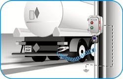
Static ground verification and interlock systems generally are line-powered. They employ approved intrinsically safe barriers to limit the monitoring circuit to safe levels but still must have proper hazardous location and safety certification. These systems typically handle ultra-safety-critical applications like loading/unloading tanker trucks and rail cars with low conductivity flammable liquids (Figure 2), IBCs, fluid bed dryers, mixers, transfer equipment and special process machines. They also are useful wherever it's highly likely that static charge will accumulate in very low MIE flammable atmospheres.
A static safety audit also requires us to consider the people working in the hazardous area. If the human body is insulated from contact with the ground, either by nonconducting shoes, insulating floors or both, static charge can start to accumulate as the person walks along the floor. After just a few steps, a fairly high potential may develop (especially in low-humidity atmospheres); if the person then approaches a conductive material at either ground or a lower electrical potential, a spark may occur. It's generally thought such sparks can reach energies as high as 30 mJ, sufficient to ignite almost all flammable vapors and gases, and many sensitive combustible powder (dust) atmospheres. These sparks can be avoided by using ground wrist-straps for sedentary workers, or static dissipative (SD) safety shoes for personnel who need to move around to carry out their tasks. In the case of the latter, it's also necessary for floor materials to be sufficiently conducting to allow a "ground leakage" path to safely dissipate any static charge as each foot contacts the ground.
In the U.S., SD footwear is manufactured according to ASTM F2413-05, which specifies maximum and minimum levels for ground leakage via the shoe. Leakage should be low enough to allow static charges to relax to ground but high enough to provide some protection against electric shock. SD footwear can be checked for ongoing effectiveness using test stations (Figure 3). These types of devices help prevent incorrect shoes being used in static-sensitive environments.
GET GROUNDED
The dangers of static electricity in hazardous areas demand a rigorous approach to plant, process and personnel safety. As the speed and scale of modern manufacturing and distribution techniques increase, and the range of materials used and processed grows, such an approach to safety becomes even more important. So, gain a greater understanding by reviewing NFPA 77 and other industry-specific codes of practice that provide practical guidance for specific situations.
GRAHAM TYERS is president of Newson Gale, Inc., Jackson, N.J. Email him at [email protected].


